
- While the pressure to get products to market is high, technologies such as USB Type-C only increase the complexity of testing.
- Understanding the connector helps identify the areas where additional tests, instruments and test fixtures are needed.
- Getting it wrong can easily extend your test time by more than 2 months at a potential cost of €1M.
- If your device fails at a USB-IF compliance workshop, according to Keysight Technologies, the cost and time delay will be even higher.
By Erik Babbé, Keysight Technlogies
Overview of the USB Type-C connector
Figure 1 shows the highly functional 24 pin connection of USB Type-C. The power pins, VBUS and GND support up to 5 amps / 20 volts / 100 watts. The four transmit/receive (TX/RX) pairs allow for one, two or all four channels to be used for data transmissions at any time and offer up to 20 Gbps speed per lane. The CC1 and CC2 lines manage the definition of the connector interface by providing three functions; orientation configuration management, supply power to cable and communication channel for power delivery. The SBU1 and SBU2 pins are side band communication channels and provide additional connections and use for protocols other than USB. A simultaneous link of USB 2 (D+, D-) can be used for standard USB 2 operations or as a supplemental link providing information for power delivery. The D+ connections are tied together, as are the D- connections to maintain the orientation independence of the connector.
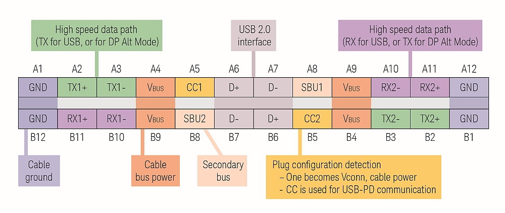
Figure 1. USB Type-C 24 pin specification.
Power Delivery (PD) dynamically manages the power allocations, adjusting voltage and current, and establishes provider/consumer roles for all the devices connected. Devices can request the power they need, and get more power when required for a specific application. PD’s bi-directional power makes it possible for a device that is being powered to also provide power to other devices. PD also enables USB Type-C to support other standards such as DisplayPort (DP) or Thunderbolt (TBT) through Alt mode.
USB Type-C Test Challenges and Solutions
Design and test engineers face several challenges as they update their device interface from the 4-pin USB standard A/B to the 24-pin USB Type-C connector. USB Type-C includes design changes that address issues with A/B type connectors/cables and offer more features and capabilities for USB Type-C enabled products. Understanding test challenges and solutions can help ensure successful USB Type-C integration and test for devices.
Power Delivery
PD’s dynamic ability and range of possible power configurations, combined with the added challenge of evolving specifications for USB 2.0, USB 3.1 Gen 1 and Gen 2, and PD compliance, make USB Type-C device test validation much more challenging than traditional USB test. Power, PHY layer, and protocol layer remain the key test categories for compliance test. Important test parameters design engineers must consider include many different voltage levels, device charging, cable functionality, and determination of provider versus consumer device status.
Figure 2 shows the host and device as dual role ports (DRP) which is aligned with the USB Type-C environment where the roles can be swapped. The state of a DRP, whether it is acting as a host or a device at a given time, is managed by the CC line as a part of the PD infrastructure. Debug of the PD protocol is one of the biggest challenge engineers face since it requires access to the CC lines and the VBUS signal for proper characterization. USB PD has specified voltage/current levels that devices can select for operation making the ability to test PD levels as devices initialize very important.
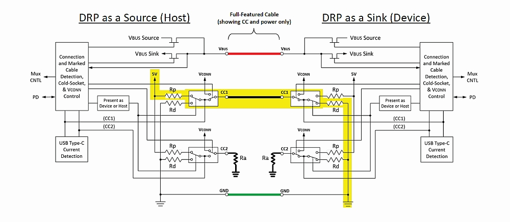
Figure 2. USB Type-C full feature implementation.
An example configuration for physical layer device test includes an oscilloscope, probes, current probe, USB PD protocol software, coupons/fixtures and a PD controller. With 300 kHz data transfer rates, a Keysight Infiniium oscilloscope of 500 MHz or more that includes a long record length to capture the entire packet is recommended. Although predominantly DC signals, most have AC characteristics and requires scope with adequate bandwidth. It is recommended to use a probe offset to see signal transients when analyzing the 5V DC supply signal as the use of a DC block filters out DC and low frequency content.
Transmit/Receive (TX/RX)
USB Type-C specifications introduce many new TX and RX test challenges. The ability to quickly and accurately measure key aspects of the transmitted eye, LFPS and LBPM timing, transmitted SSC profile, SCD signals, and to perform de-emphasis and pre-shoot will be critical for successful TX test. Flexible signal generation and bit error detection are key for RX test validation.
TX and RX compliance testing requires running compliance test patterns. These various signal patterns are generated during compliance tests, while measurements are made in a tool known as SigTest1. Each compliance test presents individual challenges. USB-IF compliance testing will require many loading and charging conditions which increases the number of tests engineers must configure and execute for each device.
For TX compliance test of USB 3.1, DP 1.3, TBT 3 and MHL, the N7015A and N7016A Type-C test fixtures, for use with Keysight Infiniium oscilloscopes, are recommended (see Figure 3). This solution offers the best signal integrity with 20 GHz bandwidth (at -3 dB), and is de-embeddable up to 30 GHz. It includes a Type-C plug interface fixture which handles connector “flip” and provides test point and probing access for transmitter and power delivery measurements.
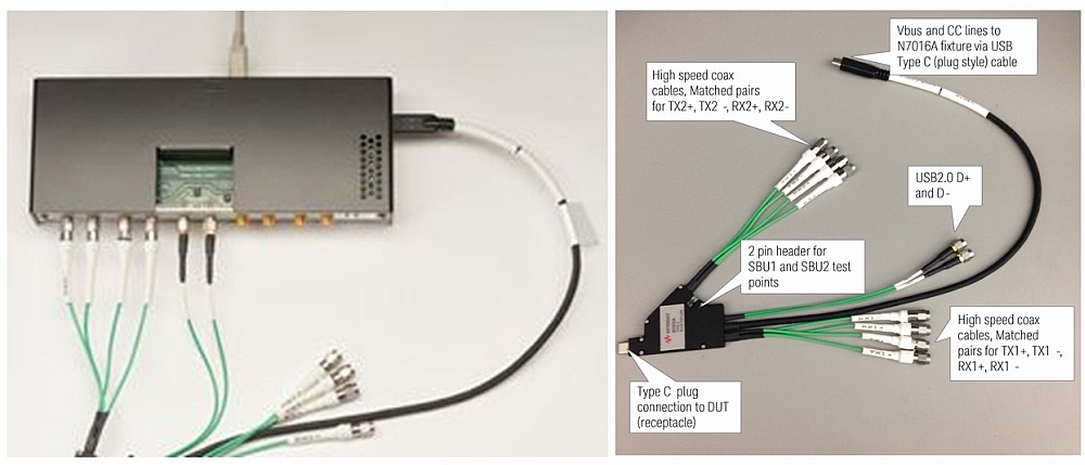
Figure 3. Keysight N7015A High Speed Type-C and N7016A Type-C low speed signal test fixtures.
The M8020A J-BERT high performance 16 Gb/s BERT has everything you need built into the equipment (de-emphasis, pattern capabilities, continuous-time linear equalization (CTLE), decision feedback equalization (DFE), the capability to create the various pattern structures, and re-sequencing). The Keysight USB 3.1 receiver test solution provides accurate and repeatable test results enabled by the M8020A J-BERT’s built-in and calibrated jitter sources (random jitter, period jitter, SSC), precise emulation of pre- and post-cursor de-emphasis, and inter-symbol interference (ISI) traces.
Cable and connector
USB Type-C channel specifications, including symmetrical connectors, high-speed data, high power, multiple data transmission types, and backward compatibility, result in many configurations that need to be tested to verify USB channel conformance. Performance of the channel in various configurations is also affected by loss, reflection, and cross-talk. More rigorous methods than what have been used in the past are needed to remove test fixture effects, to manage additional effects on channel response (Figure 4), and to manage EMI and RFI levels in the USB Type-C channel during USB compliance testing.
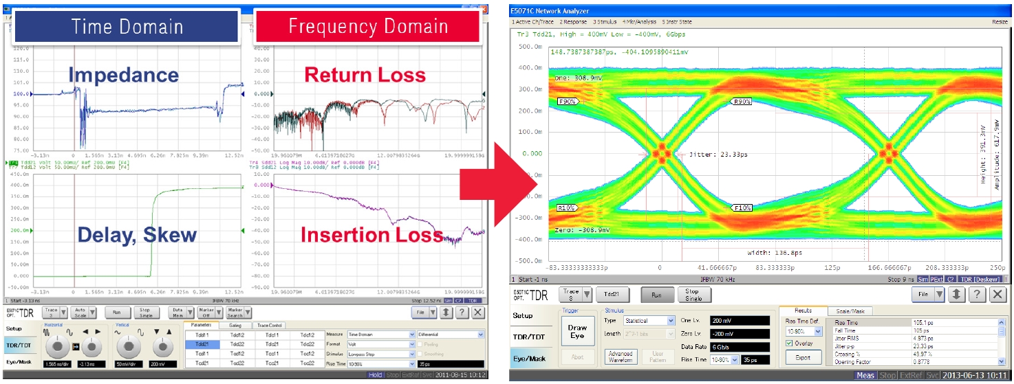
Figure 4. Channel response requires a shift in test methodology from the traditional parametric to the stressed eye testing.
Traditional cable/connector compliance tests have used a VNA for the frequency domain analysis, and a TDR oscilloscope for time domain analysis. A new recommended solution is the Keysight ENA series network analyzer with enhanced time domain analysis (option TDR) for a one-box solution that measures all the compliance parameters. A microwave electronic calibration (ECal) module, N4433A, which is controlled from the ENA USB interface, is used for ENA calibration and to remove the effects of the test setup.
Keysight Technologies’ USB Type-C test solution offers the following features :
- USB-IF certified equipment and testing for USB Rx/Tx testing
- TBT certified equipment and testing for TBT Rx/Tx testing
- VESA certified equipment and testing for DP Rx/Tx testing
Strong involvement in standards groups and related workshops, and specification development enables Keysight to bring the right solutions to the market when needed.
In addition to being certified for all the Type-C technology, Keysight’s solution is the only one that provides:
- Domain expertise
- Debug tools
- Single push of a button for full automation for all technologies
- Multiple Power Data Objects (PDOs)
- Orientation automation
- 100W capability