
A Vector Network Analyser (VNA) is probably the most versatile instrument for RF and microwave engineering tasks. This instrument can evaluate nearly all types of devices, from simple cables, filters and amplifiers to complex subsystems. Through the use of scattering parameters (S-parameters) it can evaluate the characteristics of the device under test (DUT) with a very high accuracy.
By Christian Sattler, Anritsu
While S-parameters describe a DUT very well in the linear region, it is often useful or necessary to understand the behaviour in the nonlinear region as well. IMD (Intermodulation Distortion) is a method of quantifying the nonlinear effects which become as important as harmonic and second-order distortion products in the linear region.
This is especially true for third-order intermodulation products (IM3), which are located in-band and cannot be filtered out. Hence TOI (Third-Order Intercept Point) measurement is very important to identify problems within power amplifier designs.
Creating an accurate model of a device is a key element in the simulation process. This requires accurate IMD data which can include even higher-order intermodulation products (up to IM9: the ninth order): information that is necessary for tracking the optimum spectral performance of a design. Even the asymmetrical properties of a fifth-order tone can be important for the device model. These results lead to more accurate models of devices for improved circuit simulation, and improve the chances of “first turn” design success.
A common technique for testing IMD, which has been used for some time to characterise the nonlinearity of RF and microwave components, is the use of two tones. Traditionally, this has been done at fixed frequencies using multiple signal generators, a combiner, and a spectrum analyser (Fig.1). Because the IMD products vary with frequency, these measurements can be very time-consuming as they must be repeated at various frequencies across the DUT’s operating range.

Fig.1. Traditional IMD setup based on a Spectrum Analyser
In a perfectly linear device, the two tones at the input of the DUT are amplified and only two tones are emitted at the output. In reality, multiple tones are emitted and their levels are an indication of the nonlinear properties of the DUT.
The location of the individual IM products is determined by the tone delta and frequencies of the tones. Hence there is the need to measure different IM products (IM3, IM5, etc) as well as the absolute power of the tones.
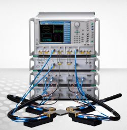
The Anritsu VectorStar MS4640B Series of VNAs can be used to quickly and accurately make small-signal S-parameter, gain compression, fixed and swept IMD measurements using a single connection to the DUT (Fig.2). This results in a tremendous advantage compared to the traditional spectrum analyser technique. In addition, built-in power calibration routines make external correction unnecessary.

Fig.2. IMD setup using the Anritsu VectorStar Vector Network Analyser
The two signals are generated in the VNA by two internal sources (up to 70 GHz) which are highly stable, synthesised generators with a wide power level range and good spectral purity. The two tones are then combined by an internal combiner and available via an external port.
This flexible hardware setup, together with the IMDView™ software option, simplifies the setup procedure and allows efficient IMD measurements over the widest range of frequencies available in a single system.
Additional information
While the traditional spectrum view is usually a good starting point for IMD analysis of a DUT, it does not show all the information necessary for an evaluation of the DUT’s non-linear behaviour. IP3 (intercept point third order) is a common specification for amplifiers, and is calculated from the amplitude of the IM3 products (Fig.3). The actual IP3 value can be referenced to the input power (IIP3) or to the output power (OIP3).

Fig.3. Intermodulation distortion products: calculation of IP3
From the standpoint of practical intermodulation distortion measurements, the products should be as high above the noise floor of the measuring device as possible. This can be achieved by setting the power of the main tones as high as possible without compressing the DUT.
In order to see the IMD performance over a wider frequency range, swept IMD is a useful tool to evaluate the DUT’s true performance. The swept-frequency IMD mode causes the centre frequency to sweep over the indicated range, which means that the two tones from the sources are also sweeping.
Measurement quality
A key factor influencing the accuracy of IMD measurements is the quality of the measurement setup: in particular, the two sources, the combining network and the receiver.
The VectorStar receiver architecture, utilising patented nonlinear transmission-line (NLTL) technology, provides an industry-leading receiver IP3 of +35 dBm. This ensures that the receiver’s IMD products are small enough not to interfere with the DUT’s IMD products.
With its high isolation, the combining network ensures that there is no interaction between the two internal sources. By using a directional coupler, a bandwidth of 70 GHz can be achieved with isolation values exceeding 20 dB. In contrast to a resistive splitter with only 6 dB isolation between the ports, a directional coupler can ensure the necessary separation between both tones. In general, 20 dB of isolation is recommended if one is to measure IMD products in the -80 to -90 dBc range. However, a newly designed power levelling circuit allows even very closely spaced tones to be achieved without problems.
User interface
IMDView™ is a software package that provides a graphical user interface (GUI) for setting up the IMD measurement. It simplifies measurement complexity and controls the VectorStar hardware for a wide range of available measurements.
A unique feature of the software is that it tracks the frequency bands of interest as well as the power levels required of the two tones. During power calibration it automatically switches the paths to reflect the required configuration. The result is calibrated tone power at the input of the DUT and corrected path loss through the combiner.
For single sweeps beyond 70 GHz, the broadband version of VectorStar operates at up to 110-145 GHz. IMDView configuration automatically monitors the system configuration, depending on whether the system is configured for baseband or millimetre-wave operation.
Outlook
Future 5G technology with extremely wide modulation bandwidths will possibly require a new concept for active device measurements. Two individual tones might not be sufficient to characterise, for example, base station power amplifiers with 100 MHz bandwidth. Instead, modulated S-parameters could be used to characterise such devices in an environment which is much closer to reality than by using simple continuous-wave tones. Anritsu has already proposed a measurement concept which goes beyond the traditional IMD measurements. Based on the VectorStar line of VNAs, this was presented first at the 2015 European Microwave Conference in Paris (Fig.4).

Fig.4. Proposed IMD measurement concept using modulated S-parameters