- It is increasingly important to understand where noise comes from in RF systems as the radio spectrum becomes more crowded and modulation schemes more complex.
- Reducing the noise present in a satellite TV set-top box can have a similar impact on the quality of the signal delivered to subscribers as specifying much larger dishes — but at much lower cost.
- This article focuses on measuring the noise generated by the system’s own electronics. This is usually due to thermal noise, arising from the vibration of conduction electrons and holes, and shot noise due to the quantised nature of current flow.
By Giovanni D’Amore, Marketing Brand Manager, Keysight Technologies
There are various ways to understand the quality of an RF receiver, such as its sensitivity or the bit error rate it achieves in decoding digital signals. But a characteristic called ‘noise figure’ can measure how much noise each part of a system creates, giving designers a consistent way to explore the trade-offs necessary (think amplifier design vs. transistor performance) to achieve the required system performance.
The noise figure F of a component or system is the ratio of the input signal-to-noise (S/N) ratio to the output S/N ratio. A noise figure is independent of an amplifier’s gain, and of the input signal level (so long as an amplifier is operating linearly). However, most amplifiers add their own noise to a signal, and a system’s noise figure will also depend on the temperature of the source that is driving it.
Noise figure is also generally a function of frequency, but independent of bandwidth. It is commonly expressed as equal to 10 log F.
Measuring a noise figure
Various issues affect how noise measurements are made. These include:
Noise power linearity
The noise power delivered by a linear two-port device is linearly dependent on the input noise power or temperature, as shown in Figure 1.
Figure 1: For a source impedance at absolute zero, the power output consists solely of added noise Na from the device under test (Source: Keysight)
If the slope of this line and a reference point are known, the output power that corresponds to a noiseless input power Na can be found. From Na, the noise figure or effective input noise temperature can be calculated.
Noise sources
One way of determining the noise slope is to apply two different amounts of input noise and measure the output power change, using a noise source. These are often built using a low-capacitance diode that generates noise when reverse biased with a constant current. Precision noise sources such as the Keysight SNS Series also have an output attenuator to provide a low standing wave ratio to minimise mismatch errors.
Figure 2: The SNS Series noise sources include a temperature sensor (Source: Keysight)
To make noise figure measurements, a noise source must have a calibrated output noise level, known as an excess noise ratio (ENR). Unique ENR calibration information is supplied with the noise source and, in the case of the SNS-Series, stored on EEPROM. When noise sources are used at temperatures other than 290K, measurements must be thermally compensated. The SNS Series noise sources include a temperature sensor that can be read by Keysight’s NFA analysers.
Measurement techniques
The Y-factor method
The Y-factor method involves connecting a noise source to the device under test (DUT) and then measuring the output power with the noise source on and off. The ratio of these two powers is called the Y-factor.
The accuracy of the relative level measurement is important. One of the advantages of modern noise figure analysers is that the internal power detector is very linear and can very precisely measure level changes.
The Y-factor and the ENR can be used to find the noise slope of the DUT, as shown in Figure 1. Since the calibrated ENR of the noise source represents a reference level for input noise, an equation for the DUT internal noise, Na, can be derived. From this we can then derive an expression for the total system noise factor, FSYS, which represents the noise contribution of all parts of the system.
When the noise figure is much higher than the ENR, the device noise tends to mask the noise source output and the Y-factor tends to 1. Because it is difficult to measure small ratios accurately, the Y-factor method is not used when the noise figure is more than 10dB above the ENR of the noise source.
The equation defining the Y-factor can also be elaborated to correct for the condition when the noise source cold temperature, Tc, is not at the 290K reference temperature, To.
The signal generator twice-power method
This approach involves measuring the output power with the device input terminated with a load at a temperature of approximately 290K. Then a signal generator producing a signal within the measurement bandwidth is connected and its output power adjusted to produce a 3dB increase in the output power of the DUT. If the generator’s power level and measurement bandwidth are known, it is possible to calculate the DUT’s noise factor.
There are limitations to this approach. The noise bandwidth of the power-measuring device must be known, perhaps requiring a network analyser. The output power must be measured on a device that measures true power, since both noise and a continuous wave (CW) signal are present. Thermal power meters measure true power very accurately but may require a lot of amplification to read a low noise level, and will also need a bandwidth-defining filter. Spectrum analysers have good sensitivity and a well-defined bandwidth but the detector may respond differently to CW signals and noise.
The direct noise measurement method
In this approach, the output power of the device is measured with an input termination at a temperature of approximately 290K. If the gain of the device and the noise bandwidth of the measurement system are known, the noise factor can be determined.
As before, the noise bandwidth must be known and the power-measuring device may need to be very sensitive. Unlike the twice-power method, the DUT gain must be known and the power detector must be able to measure levels (not just ratios) accurately.
Noise figure measuring instruments
Noise figure analysers
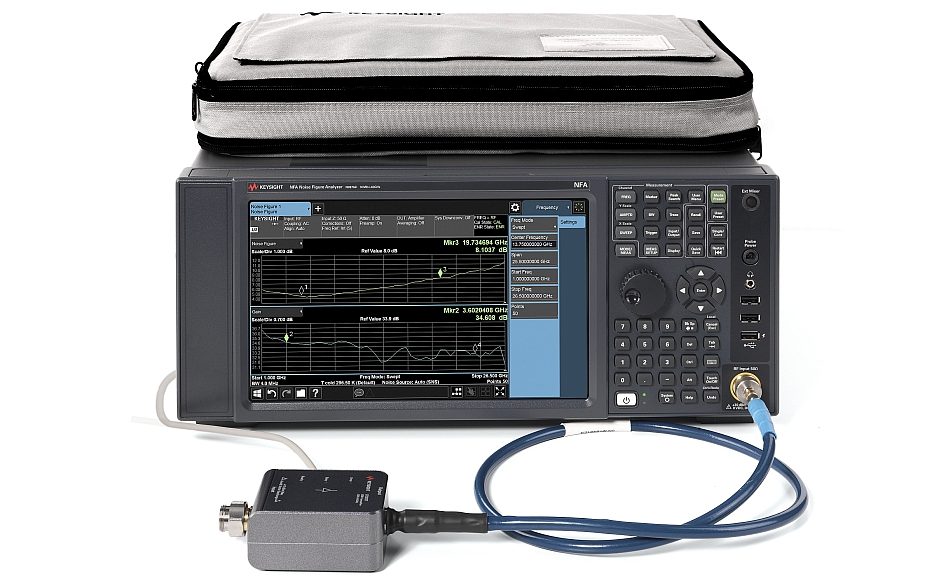
A noise figure analyser has a receiver with an accurate power detector and a circuit to power the noise source. It allows ENR to be entered, and can display the noise figure for the frequency to which it is tuned. It computes noise figures using the Y-factor method.
Figure 3: NFA series noise figure analyser (Source: Keysight)
A noise figure analyser can usually display swept frequency noise figure and gain plots, with markers and limit lines.
Signal/spectrum analysers
Signal/spectrum analysers can be enhanced with additional software and a controller to measure noise figure using the methods outlined above. The noise figure measurement application on the X-Series signal analysers provides noise figure and gain measurements very similar to those on the NFA Series noise figure analysers.
Signal/spectrum analysers, even with their internal preamps, do not have an instrument noise figure as low as a dedicated NFA, so to measure very low- gain devices it’s best to use a dedicated NFA or add a low-noise pre-amplifier.
Network analysers
Network analysers are widely used as multi-function instruments in industry, and some offer noise figure measurements. They can usually also measure device gain and matching. Some are slightly limited for noise figure measurements because if they use double side-band receivers, the noise figure will be measured at two frequencies and then corrected. This works on narrow measurement bandwidths, but at wider measurement bandwidths can introduce errors. One problem that you face with classic noise figure analysers, like a spectrum analyser, is the impossibility to compensate for elements present in your measurement chain, like cables and adapters, in addition to the device under test. The noise figure analyser has some compensation features but those are scalar by nature, so this adds uncertainty to the overall measurement. Thanks to their vector calibration capabilities, network analysers are able to perform this correction in a very accurate way. Measurement techniques including s-parameter and source-matching correction allow the creation of a setup that can measure the noise characteristic of the device and compensate for the errors induced from the measurement setup itself.
Noise parameter test sets
A noise parameter test set is usually used with software, a vector network analyser and a noise analyser to make a series of measurements that enable the user to work out the noise parameters of a device.
A noise source is coupled to the test set to allow noise figure measurements at different source impedances. The test set has a tuner that presents various source impedances to the DUT. The corresponding source impedances are measured with the network analyser. From this data, the complete noise parameters of the device, including the minimum device noise figure, the optimum source impedance, and the effect of source impedance on noise figure, can be calculated. A similar approach can be used to determine gain parameters. The parameters derived from this kind of setup are very important especially during the design phase of a component.
Power meters and true-RMS voltmeters
Power meters and true-RMS voltmeters can be used to measure noise figure with the methods described above. Being broadband devices, they need a filter to make their bandwidth narrower than that of the DUT. Such filters are usually fixed in frequency and only allow measurements at this frequency. Power meters are most often used to measure receiver noise figures where the receiver has a fixed intermediate frequency and a lot of gain.


