
dbCalculator manual
dBCalc – User Manual of freeware for dB dBm and radio computing
Thank you for using dBCalc, a platform – independent* freeware application for RF engineers based on html and javascript.
This documentation contains descriptions of each feature that dBCalc offers, experienced RF engineers may find this unnecessary and will use dBCalc without this user manual.
Operation :
Besides conversion of Voltage and Power ratio to dB and vice-versa, dBm, V, A, W, dBµA, dBV, dBµV conversions features also attenuator, matching pad, VSWR and path loss calculations.
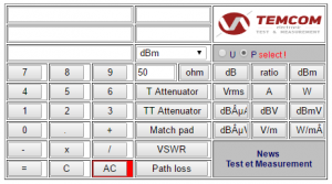
Quickstart :Enter the value and the unit to be converted : for example ‘ 30 ‘ and choose ‘dBm’ (default unit), then press the key of the unit in which you wish to convert the value (e.g. : ‘ W ‘).
For ‘dBm’ ‘voltage/current’ conversions it is necessary to choose the impedance (default value = 50 ohm) !
Attention:
For ‘dB’ ‘ratio’ conversions and for ratio ‘T’ ‘TT’ attenuator computing, it is important to select either ‘P’ or ‘U’ (10·log or 20·log…).
The source impedance ( Ri ; default value = 50 ohm) can be set either by entering the corresponding ohm value in the x dsiplay and transfered with the “ohm” button or by click with left mouse button in the r-display and then using computer keyboard.
– Choose unit to be converted with selector (default value = “dB”)
– Enter the value to be converted by means of the keyboard field
(or by click with left mouse button in the x-field and using the computer keyboard)
– Push one of the conversion keys in order to obtain the corresponding conversion.
Decibel :
The Decibel represents a logarithmic relationship between two power levels.
Derived from the Bel (in honor of Alexander Graham Bell) – the Decibel corresponds to 1/10 of a Bel .
The unit – one Bel at its origin – represents the power ratio of 10 to 1 between the intensity (power) of two sounds.
A power ratio of 100 (1:1) = 0 Bel ; 101 (10:1) = 1 Bel ; 102 (100:1) = 2 Bels and 103 (1000:1) = 3 Bels……
The above shows the logarithmic relationship : the logarithm of 100 to the base 10 is 2 (corresponding to 2 Bels) etc…
The exact relationship for an amplifier is given by the formula : Bel = log(P2/P1)
P2/P1 represents the power ratio of the output power versus the input power.
For an attenuator the formula is : Bel = log(P1/P2)
P1/P2 represents the power ratio of the input power versus the output power.
As the bel prooved to be a to large unit, so the decibel or dB, was adopted.
10 decibels make one bel thus the formula becomes :
Decibels (dB) = 10 · (P2/P1)
dB atten = 10 · log (P1/P2) ≡ 20 log (U1/U2)*
dB gain = 10 · log (P2/P1) ≡ 20 log (U2/U1)*
* However this is only true if R1 = R2, remember : P = U²/R
An important value to remember : 10 · log 2/1 = 3.01 dB ; 100.301 = 2, thus a gain of ≈3dB doubles the power and an attenuation of ≈3dB halves the power.
dBm :
dBm indicates dB referenced to 1.0 milliwatt. One milliwatt = zero dBm. Thus P1 in above dB equations becomes 1.0 mW consequently 10 dBm = 10 mW, 30 dBm = 1W…
dBV :
dBV indicates dB referenced to 1.0 V. One volt = zero dBV. Thus U1 in above dB equations becomes 1.0 V consequently -60 dBV = 1mV…
dBµA :
dBµA indicates dB referenced to 1.0 µA. One microampre = zero dBµA consequently 120 dBµA = 1A…
dBµV :
dBµV indicates dB referenced to 1.0 µV. One microvolt = zero dBµV. Thus U1 in above dB equations becomes 1.0 µV consequently 120 dBµV = 1V…
VSWR – return loss :
Choose either ‘dB’ ‘VSWR’ ‘ratio'(reflection coefficient or return Power depending on U or P setting) mode, enter value and push the corresponing (dB or VSWR) button. VSWR of 1 : no return power (adaption); VSWR = infinity : return loss = 0 dB (all power is reflected)
VSWR used to be the indicator for adaption of RF devices. The “Voltage Standing Wave Ratio” on a transmission line caused by the incident and the reflected wave corresponds to Vmax / Vmin mesured on a sliced transmission line with an RF voltmeter (incident wave in phase with reflected wave = Vmax; incident wave in phase-opposition with reflected wave = Vmin).
Modern measuring instruments (Network Analysers) measure the reflected wave with the help of directional couplers or VSWR-bridges. The ratio of Vref/Vinc is the reflection coefficient (Γ). If 10% of the forward voltage is reflected (VSWR = 1.222) , this means that (Γ) = 0,1 and the return-loss is 20 dB, indicating that 1% of the forward power is reflected to the source. Thanks to the formula Z =( 1+Γ) /(1-Γ) the load impedance (Z= R + jX) can be computed (or obtained with the help of the Smith Chart).
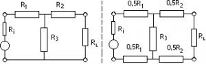
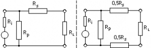
Attenuator calculation :
(a = voltage attenuation ; Ri = internal resistance ; RL = load resistance)
Choose dB mode ; enter the attenuation value, then choose either T or TT and read the corresponding resistors
Choose dB mode ; enter value of Ri in r-display (Default = 50 Ohms) and value of attenuation in the dB display, then push “T Attenuator”
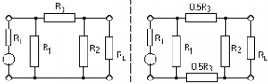
 TT – Attenuator
Choose dB mode ; enter value of Ri in r-display (Default = 50 Ohms) and value of attenuation in the dB display, then push “TT Attenuator”
asymmetric – symmetric
Matching pad calculation :
Choose dB mode ; enter value of Ri in r-display (Default = 50 Ohms) and value RL in X-display, then push “Match pad” Caution: the attenuation value obtained is applies to the voltage (on different impedance, the attenuation of the power is different from that of the voltage… to see chapter dB)!
For example for a match pad (minimum loss pad) some user look for loss of voltage : from 75 to 50 ohms, it is 7.48 dB ; from 50 to 75 ohms it is 3,96 dB. However the only correct expression is power loss (see above mention about dB) : it is identical for the two directions, i.e. 5.72 dB.
asymmetric – symmetric
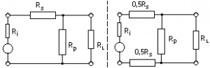 RL > Ri
 asymmetric – symmetric
Path Loss
Choose dB mode, enter frequency (in MHz) in upper display and distance (in km) in middle display then press ‘Path loss’ button.
Propagation of radio waves follows the same basic optical rules as any electromagnetic beam (light for example) like reflection, refraction and diffraction. The inverse-square law for electromagnetic radiation implies a free space path loss proportional to the square of the distance.
If elctromagnetic energy is emitted by an isotropic radiator, that energy propagate evenly to all directions. Areas of same power density therefore form spheres around the isotropic antenna. The power density Pd (W/m²) at a certain distance can thus be calculated :
Pd (W/m²) = Pt(W) / spheric surface … = Pt / 4·π·r²
For free space propagation of waves in the radio channel, the path loss model is :
Lo = (4 · π · D / λ)² ; = (4 ·π · d · f / c)² ; = -32,44 – 20·log(f[MHz]) – 20·log(D[km])
Note : ground reflections can significantly influence path loss. Free space loss needs also to be corrected for significant diffraction losses if 1st Fresnel Zone Clearance is not respected.
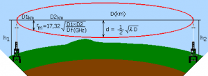
At 0.9GHz (λ = 0.33m) and D = 10 km : 100% clearance d = 28.86 m, at D1 =2km and D2 = 8km, 100% clearance is for r = 23.09 m.D = √(4*((Rteff +h)² – (Rteff+hF)²)… allows to compute line of sight distance (D) as a fonction of antenna height. hF= Fresnel clearance; Rteff = 8500 km, 4/3 of the 6370 km earth radius.
Disclaimer
The software is provided “as is”. In no event shall the autor or distributor be liable for any consequential, special, incidental or indirect damages of any kind arising out of the delivery, performance or use of this software. The software has been developed with great care, however it is not possible to warrant that the software is error free. The software is not designed or intended to be used in any activity that may cause personal injury or any other severe damage or loss.
Copyright
Modification, translation or partial use the software is prohibited. Copies of the software may be given free of charge (except a reasonable fee for material and/or communication costs) to others on the strict condition that this is done by copying the original, unaltered software. For a licence against à fee (for example with your logo) please contact info@temcom.com