More and more of today’s cars include infotainment systems that allow occupants to communicate with the outside world. Good reception in cars is ensured by an increasing number of transmit and receive antennas from a variety of radio systems located in close proximity to one another. However, mutual interference is an inherent risk with this type of “in-car coexistence” that must be prevented during development.
By Christoph Wagner, Rohde & Schwarz
According to a study by Accenture, more than 48 percent of car buyers today are more interested in electronic features such as driving assistance and infotainment systems than they are in driving performance. Traditional car manufacturers have long had a presence in the California Silicon Valley as they worked toward early adoption of intelligent, networked mobility, with a view toward enticing especially young buyers into an automobile purchase. The melding of automobile and modern information technology into a smart car is no longer a vision for the future, but rather is now a reality on our roads.
An important function of the smart car is the ability to wirelessly connect smartphones to the vehicle infotainment system using noncellular wireless technologies such as WLAN or Bluetooth®. This connection is used to sync data from a mobile phone (e.g. contacts and music) with the on-board unit so that it is available to the car occupants while driving. Car manufacturers offer integrated WLAN hotspots for connecting smartphones and tablets to the Internet. Cellular standards such as WCDMA and LTE can be used to establish a connection to the mobile radio network. The Bluetooth® standard is operated in the license-free ISM band from 2.402 GHz to 2.480 GHz. For the WLAN standard, country-specific frequencies are available within the 2.4 GHz and 5 GHz bands. The use of multiple wireless communications standards such as LTE, WLAN and Bluetooth® in parallel is known as coexistence. Leakage into adjacent channels can lead to quality problems, a reduction in data rates or even to a complete failure.
Radio systems in very tight spaces
Simultaneous collocation of various radio systems is a longstanding issue that is regulated by means of international frequency plans and technical specifications. What is new, however, is that these systems must now both transmit and receive in extremely close proximity. The primary independent standardization bodies working on this topic are the 3rd Generation Partnership Project (3GPP) for cellular standards and the Wi-Fi Alliance® for the WLAN standard. These groups specify, among others, limits for RF leakage into other frequency ranges, which are defined by the adjacent channel leakage power ratio (ACLR), for example. This parameter specifies the ratio between the transmit power of the wanted signal and the lowest possible power that is leaked into the adjacent channel. Another important parameter when verifying radio standards is the spectrum emission mask (SEM). This parameter uses tolerance characteristics to describe the permissible signal level versus time both inside and outside the transmission band allocated to a standard in order to limit the interference in the adjacent channels and in other frequency bands.
The passenger compartment in a car poses a particular challenge for developers because of the increasing number of transmit and receive antennas that are collocated in very close proximity in a mostly shielded space. An additional consideration are the associated reflections. A transmit signal will always affect other systems more here than it would in an open area or a larger space. This is particularly problematic because the described noncellular standards are operated in frequency bands that lie very close to one another. The LTE standard will also fall within this range depending on which frequency bands are used. For example, LTE time division duplex (TDD) band 40 lies only 1 MHz below and the LTE frequency division duplex (FDD) band 7 uplink only 17 MHz above the 2.4 GHz WLAN band (Fig. 1). As a result, transmit signals can show up as interference in adjacent receivers and cause overdrive, making it impossible to receive wanted signals. The utilization of the various LTE bands varies by country and network operator, and because there is no way to predict when or where a car might pass into an area serviced by a different band, developers must take all possible scenarios into account in order to ensure interference-free operation. And the list of potential interferers is expanding, as the satellite-based navigation systems (GNSS) such as GPS, Glonass and Galileo found in vehicles can also be impaired by LTE bands 7, 13 and 14.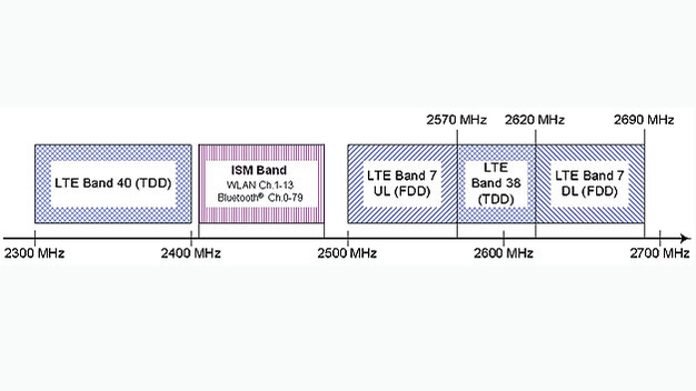
Fig. 1: The license-free ISM band is used by WLAN and Bluetooth®, in addition to other radio services. The lower band lies very close to LTE band 40 and the upper is adjacent to LTE band 7.
Digital dividend
To address the need for additional frequencies for mobile Internet access, in 2009 the International Telecommunication Union (ITU) released the 800 MHz band for mobile radio applications, followed this year by the 700 MHz band (digital dividend 2) which previously had been reserved exclusively for broadcasting. This means that car radios and entertainment systems that receive terrestrial TV signals can be impaired by mobile radio signals. As a result, it is essential that developers include all broadcasting signals in any comprehensive test scenario.
There are several possible approaches for improving the reception quality in automobiles. Physically distancing the transmitter from the receiver, i.e. decoupling the antennas, is not practicable because the lack of space is at the root of the problem in the first place. The usual RF shielding methods are likewise not sufficient to resolve the problem. On the other hand, it is possible to use additional bandpass filters on the transmit antennas for WLAN and Bluetooth® in order to reduce RF leakage into the at-risk LTE bands. The transmit powers of the individual applications can be reduced as a result of the limited space, thus also reducing any possible unwanted emissions. In the case of noncellular standards, this can be implemented on an individual basis. This is not an option for cellular standards, however, because the transmit power is controlled by the base station.
The essential difference between WLAN and Bluetooth® – besides the range – is that WLAN uses fixed frequencies while Bluetooth® employs frequency hopping. The Bluetooth® signal switches randomly between 40 possible channels in a 2 MHz grid (BT4.0) up to 1600 times per second. This prevents the signal from permanently affecting a fixed WLAN signal in the 2.4 GHz band. The reception quality within the vehicle can be further improved both in the frequency and in the time domain. The highly integrated computer chips found in today’s infotainment systems incorporate the various standards. The frequencies to be used for the various applications are already known in the baseband of this chip. This means that a “black list” can be defined for the Bluetooth® signal’s frequency hops, listing the channels that could be impaired by an LTE signal and therefore should be avoided. This process is known as adaptive frequency hopping.
To prevent impairment of GNSS signals by LTE, it makes sense to employ early detection of data transmissions in the time domain. For example, if an LTE chip is aware that a GNSS packet with a length of 20 ms will be transmitted, the chip can interrupt its own activity for e.g. 15 ms so as not to disrupt the entire transmission, while keeping the interruption short enough that it is not perceived by the subscriber.
The receive quality of audio and video systems in cars can be improved by using flexible diversity reception. The signal is received and assessed by up to three RF tuners, with only the best signal being processed. An additional antenna (3+1 principle) is used to monitor the frequency spectrum. This antenna gathers information about possible interference as well as improved reception on other frequencies, which it then passes on to the other receivers so that they can switch frequencies.
Uninterrupted detection of unwanted signals
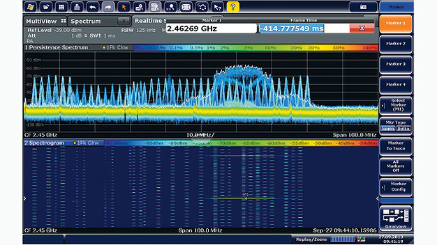
A spectrum analyzer can be used to capture and display the parameters of unwanted signals in the frequency domain. This information can be used to determine the origin and type of unwanted signal. In practice, these signals can also be very brief in duration while having the same effect. This is why a real-time spectrum analyzer is often used. Instruments like the R&S®FSW from Rohde & Schwarz, when equipped with the R&S®FSW-K160RE real-time option, measure continuously in real-time operation, thus capturing every event for analysis, no matter how brief. Spectrogram mode is especially suited for verifying the frequency hopping of Bluetooth® signals (Fig. 2), as it depicts how the signal’s spectrum fluctuates versus time. This provides a good overview of the signal behavior and allows assessment even for brief signal impairments. Only additional testing can determine the extent to which the individual radio systems are impaired.
Fig. 2: In spectrogram mode, the individual frequency hops of a Bluetooth® signal can be easily viewed and followed.
Receiver sensitivity assessments
Coexistence measurements are used to determine the degree of desensitization, i.e. the decrease in receiver sensitivity as a result of strong RF leakage in an adjacent signal. An important assessment criterion in determining the sensitivity of a receiver is the bit error rate (BER). The device to be tested receives a certain number of bits within a defined time frame, which are then compared against a reference signal. For WLAN and Bluetooth®, this is known as the packet error rate (PER) and for LTE it is the block error rate (BLER). With this measurement, the error rate can be seen to increase below a certain receive level (Fig. 3, blue curve). If an additional unwanted signal is received at the receiver input, the curve slowly shifts to the left (Fig. 3, red curve). The sensitivity of the receiver decreases dramatically.
Fig. 3: The blue curve shows a typical WLAN PER progression without interference. As the receive level decreases, the error rate will increase. This effect occurs sooner when interference is present (red curve), and the sensitivity of the receiver decreases significantly – known as desensitization.
Multistandard-capable radio communication testers are especially suited to coexistence measurements. With the flexibly configurable R&S®CMW500, Rohde & Schwarz offers a test platform that can measure all major cellular and noncellular wireless communications standards for multiple radio systems simultaneously. As a result, both the wanted and the unwanted signal can be generated using a single instrument. To ensure a realistic simulation of the signal propagation within the passenger compartment along with any reciprocal interference, the test setup must always include a connection via the air interface instead of the more easily implemented cable connection. For small setups, a compact test chamber can be used for this purpose. The R&S®CMW500 frontend includes multiple RF connectors for the transmit and receive signal paths, eliminating the need for a switch matrix in the simplest scenarios.
A further multistandard platform is recommended for simulating diversity reception of broadcast signals. The R&S®BTC broadcast test center uses two independent real-time signal paths and up to eight arbitrary waveform generators to generate all of the required RF signals for international TV and broadcast standards, including the relevant interferer signals (Fig. 4). As a result, developers have access to signals from local public networks as well as those from other countries required for a globally valid scenario.
Fig. 4: The R&S®BTC can be used for complex diversity reception scenarios for broadcast signals. The frequency and level of the individual wanted and unwanted signals can be adjusted in real time.
Outlook
The described scenarios are not only about permitting users to make phone calls from the car or to connect their portable devices to the vehicle infotainment system. Future cars will have a fixed connection to their environment. This connection can provide quick access from the car to the company server or the home A/C system or from the automotive service center back to the car to permit remote fault diagnostics. WLAN standard 802.11p permits the exchange of information between vehicles, for example to provide a warning about an accident, roadwork or icy road surfaces. Europe, the USA, South Korea and Japan have already allocated frequency bands for this purpose. To further optimize reception in the car, future automobiles are planned to be equipped with their own mobile stations (LTE hotspots). These hotspots, which are already being used in buildings, not only ensure a good connection between the car antenna and the wireless devices, but also permit individual adjustment of the transmit power to reduce interference within the vehicle.
Author: Christoph Wagner heads business development for the automotive market segment at Rohde & Schwarz in Munich. He studied communications engineering at the Deutsche Telekom University of Applied Sciences in Berlin as well as the Copenhagen University College of Engineering.

