
- The NB-IoT communication technology has been designed so that the connected devices can transmit information over a long range with low power consumption.
- Anritsu explains in this article how the maximum data rate is determined and how to measure the upload rate during the test of a NB-IoT modem.
The NB-IoT standard has been developed by 3GPP to provide wireless connectivity for the anticipated billions of devices and sensors that will enable the smart cities, homes and businesses of the future. In comparison to existing cellular standards, NB-IoT had been designed to meet the requirements of lower power consumption, increased range and dense deployments catering for devices such as smart meters, actuators and sensors that send and receive only small amounts of data in the order of bytes on an infrequent basis.
When considering the adoption of NB-IoT technology for a device or service it will be important to understand what the typical data rates are that can be achieved and what variability exists in order to best optimise the applications and services that may be deployed around the NB-IoT devices. It may also be useful to allow for events such as remote device maintenance or software upgrades which could command higher data rates compared to business as usual operation.
Most figures relating to NB-IoT data rates quote “peak” rates in the range of 200kbps in the downlink direction and 250 kbps for the uplink. Being described as “peak” suggests that these are not the rates that a device is likely to experience and this is indeed the case.
In this article, we will look at how the peak data rate is determined but also try to explain why devices (release 13 category NB1 devices) will not be able to sustain these peak data rates. In fact the data rate is more likely to be a factor of 10 less than these peak rates due to reasons such as data scheduling, support for only a single HARQ process and the overhead of RLC/MAC headers. For devices operating on the fringes of cell coverage the data rates will be reduced further due to the reduced uplink subcarrier spacing (3.75 KHz) and the need for data repetitions.
NB-IoT Peak Data Rates
When a NB-IoT device is in a connected state, user data transmission in the downlink will occur on the Narrow Band Physical Downlink Shared Channel (NPDSCH) and in uplink on the Narrow Band Physical Uplink Shared channel (NPUSCH). The UE first has to decode the dedicated control information (DCI) sent on the Narrow Band Downlink Physical Control Channel (NDPCCH) in order to determine when and how the data transmission is to be scheduled.
Depending on the amount of data to send, available network resources and radio conditions the transport block size will vary. Considering the downlink direction first and assuming maximum allocation is given to the UE, the data can be transmitted using a maximum transport block size of 680 bits taking a minimum of 3 subframes (where an NB-IoT subframe is of 1ms duration). This transport block size information can be determined from 3GPP 36.213 Tables 16.4.1.3-1 and 16.4.1.5.1-1. Just considering these 3ms of transmission the data rate would be 680/3ms=226kbs, close to the 200kbps peak downlink data rate mentioned above.
In the uplink direction, the maximum transport block size is 1000 bits and could be transmitted in the best case by using 4 resource units. A resource unit is the minimum uplink transmission unit used in NB-IoT and is formed from a number of subcarriers for a period of time measured (time in this case being measured in slots, where one subframe consists of 2 slots). Referring to 36.213, tables 16.5.1.2-2 and 6.5.1.1-2 and 36.211 Table 10.1.2.3-1, using NPUSCH format 1 for the data transfer and 15 kHz subcarrier spacing the optimum resource unit allocation of 12 subcarriers results in a transmission over 2 slots. As 4 RU’s are required to send 1000 bits this would result in a transmission over 8 slots (or 4 subframes) giving a peak data rate of 1000/4ms=250kbs at the physical layer.
Typical NB-IoT Data Rates
The above explanation confirms that the NB-IoT physical layer is capable of instantaneous peak data rates of 226 Kbps in the downlink direction whilst up to 250kbps in the uplink, however sustained data rates will likely be a factor of 10 less due to several factors.
Firstly, the protocol doesn’t allow for new data to be scheduled in consecutive subframes and as there is only a single HARQ (Hybrid Automatic Repeat Request) process, data first has to be acknowledged by the recipient before the next transport block is scheduled (although this acknowledgement is optional in the downlink and under control of the network).
Also, very significantly, in order to greatly increase the link budget by 20dB over existing cellular technologies (e.g. GPRS) allowing for extended coverage the NB-IoT protocol employs data repetition. The NPDCCH, NPDSCH and NPUSCH channels can be configured to repeat transmissions in consecutive subframes. For instance, DL transport blocks carried by the NPDSCH could be repeated up to 2048 times and conversely 128 times for the NPUSCH.
So, what are the typical sustained data rates that could be achieved if no repetitions have been configured? Essentially the timing of the downlink data is detailed in figure 1.
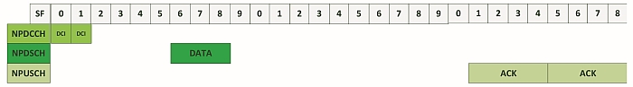
The downlink control information (DCI) will occupy 1 subframe but as shown in figure 1 is likely to be repeated multiple times in consecutive subframes (up to 2048 repetitions is configurable). The delay between the DCI and NPDSCH reception is a minimum of 4 subframes but the DCI information will indicate if a scheduling delay is also to be applied which is in addition to the 4 subframes.
Following the reception of the NPDSCH the UE will (if instructed by the network) acknowledge the reception of the downlink transport block using the NPUSCH (using NPUSCH Format 2). The ACK will be at least 12 subframes later, requiring 4 slots but similar to other transmissions could be repeated in consecutive slots if the network has signalled the UE to do so.
Assuming the NPDCCH and acknowledgement is repeated twice and no scheduling delay is configured by the network for NPDSCH reception or ACK transmission, the time to decode the DCI and 680-bit transport block and subsequently send the acknowledgement would be 25ms.
If continuously repeated this would be a sustained data rate of 27 kbps (680/25ms).
However even this data rate is unlikely due to the scheduling of the NPDCCH (which will be required to fall within certain subframes to satisfy the UE Specific Search space), ignoring subframes used for SIB transmission and due to the Half Duplex nature of the standard allow the UE switching time between uplink transmission and downlink reception. Then of course there will be other devices that the network will need to schedule resources for, so the DCI will not always be for the device in question and the NW will specify a scheduling delay in order to interleave NPDSCH transmissions intended for different devices.
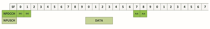
In the uplink direction, the situation is similar except the delay between DCI reception and NPUSCH transmission is at least 8 frames. The timing between NPUSCH and receiving network acknowledgement of the transport block is at least 3ms.
Assuming NPDCCH is repeated twice but only a single transmission of the transport block (1000 bits) on NPUSCH, the time of the overall uplink transmission would be 19ms giving a sustained data rate of 52kbs (1000/19ms).
Again, as for the downlink direction this doesn’t take into account the scheduling of other devices and the need to avoid SIB transmissions. Also, it assumes the UE has reasonably good coverage and the most efficient NPUSCH configuration using 15 KHz subcarriers is used for transmission.
Importance of Testing
To understand how a module employing NB-IoT behaves under varying network conditions it is important to test in a lab against a base station simulator.
Using a live network for the testing although also important could mask many problems.
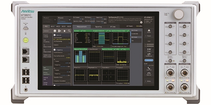
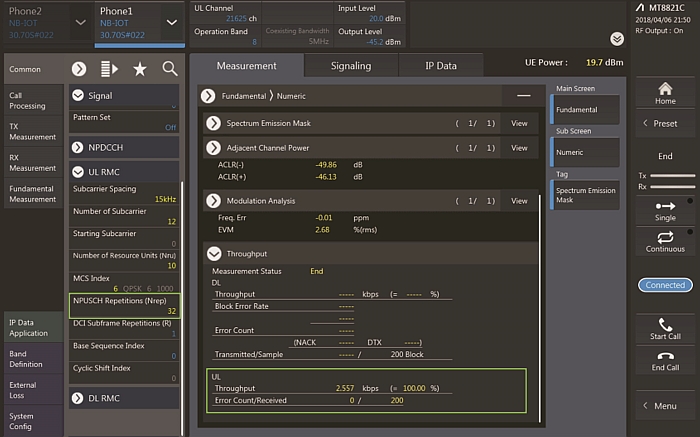
A base station simulator such as Anritsu’s MT8821C Radio Communications Analyser provides the flexibility to modify the data allocation provided to the UE. Repetition, transport block size and sub carrier spacing are several of the settings that can be controlled to vary the data rate conditions that a UE could experience in the field.
Figure 4 shows an actual uplink throughput measurement while testing a NB-IoT modem. The result of 37kbps as expected being lower than the “ideal” value previously calculated.
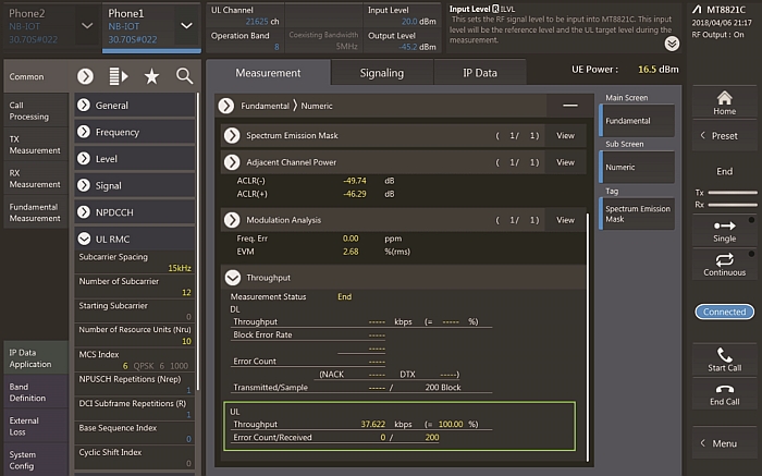
If repetitions are then applied to the NPUSCH transmission (a simple parameter change) as can be seen in Figure 5 such that the uplink data is repeated 32 times the impact to the data rate can be clearly seen.
Testing the various conditions will ensure any applications behave as intended even if the device is operating on the fringes of cell coverage or in a dense deployment scenario where data rates could be bits per second rather than kilobits per second.
References
3GPP TS 36.331 Evolved Universal Terrestrial Radio Access (E-UTRA); Radio Resource Control (RRC); Protocol Specification
3GPP TS 36.213 Evolved Universal Terrestrial Radio Access (E-UTRA); Physical layer procedures
3GPP TS 36.211 Evolved Universal Terrestrial Radio Access (E-UTRA); Physical channels and modulation