

- VCSEL diodes are the key components of Lidar systems commonly used for laser distance measurement.
- Lidars are used in a variety of 3D environmental imaging and mapping applications. In particular, they are embedded in autonomous vehicles for the detection of objects surrounding them as well as for 3D recognition, robotics, environmental monitoring, etc.
- The performance and characteristics of Lidar are partly based on those of VCSEL (vertical-cavity surface-emitting laser) diodes, which must therefore be rigorously tested in order to ensure the reliability of Lidar.
- However, as Andrea Vinci, Technical Marketing Manager at Tektronix, explains, testing VCSEL diodes requires specific test procedures and the use of appropriate instruments.
- To overcome these challenges, Tektronix has incorporated pulse optimization technology into Keithley’s 2601B-Pulse sourcemeter to perform tests that meet the specific requirements of VCSELs and other components requiring the use of very short pulses and relatively high current intensities.
LiDAR (Light Imaging, Detection And Ranging) emits an invisible beam of light via laser diodes that scans the surrounding environment. It detects targets at varying distances from its sensors to create a 3D map of nearby objects. Lidar can be used for a variety of applications. In particular, it is at the heart of critical functions for detecting pedestrians, animals or other objects with which an autonomous vehicle could collide.
Like radar, Lidar uses the principle of echolocation. However, whereas radar emits electromagnetic waves at frequencies of the order of 1 to 100 GHz, Lidar emits light pulses with wavelengths ranging from ultraviolet to infrared. When the light wave emitted by the lidar is reflected from a target, the distance to the target is determined by measuring the delay between the emission of a laser pulse and the reception of the reflected pulse. The frequency offset between the reflected and received waves is used to determine the speed of the target.
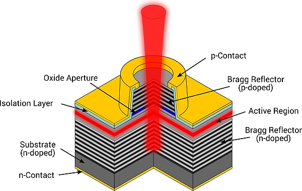
A Lidar is based on VCSEL (vertical-cavity surface-emitting laser) diodes. These are semiconductor laser diodes emitting a laser beam perpendicular to the surface, unlike conventional semiconductor lasers emitting from the edges of the semiconductor chip .Several tens of thousands of diodes can be fabricated simultaneously on a wafer. VCSEL diodes emitting at wavelengths between 650 nm and 1,300 nm are typically produced on gallium arsenide (GaAs) wafers.
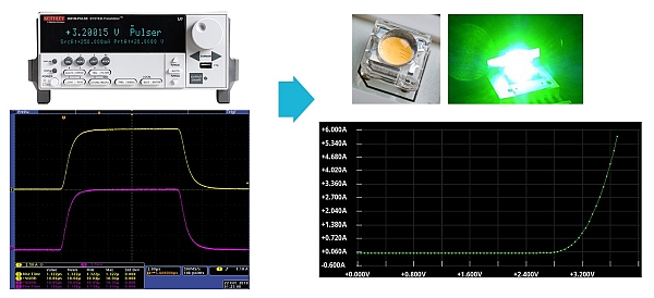
Given the mission-critical requirements for VCSELs that are used in automotive LIDAR applications, each VCSEL must be tested to ensure no faulty components are sold and utilized in a vehicle, to avoid the potential for a catastrophic incident. LIDAR systems are composed of an array of VCSELs, which presents testing issues for engineers who are faced with the challenge of testing each individual VCSEL while minimizing any potential damage to the VCSEL, adjacent VCSELs and the test apparatus itself. For VCSEL testing, design and test engineers create automated LIV (light vs. current vs. voltage) measurements, which are used to determine key specifications in the design phase. The VCSELs are then tested to ensure those specifications are met, along with meeting quality, reliability, and safety standards.
Testing these devices requires very short operating pulses and specific drive currents. Instruments must be able to provide high levels of current but at very short pulse widths, typically less than 100μseconds. Without very short pulse widths of current, device self-heating can cause inaccurate optical measurements, including improper wavelength measurements. Also, applying high levels of currents to devices over a period of time can result in device damage, potentially causing damage to probe tips when VCSELs are tested directly on the wafer.
In addition, research and development engineers testing VCSELs face challenges with the synchronization of multiple instruments, pulse tuning, achieving the necessary throughput in productions, and overall reliability costs. This testing often requires multiple instruments, such as a separate pulsing current source for the output, a voltage source, a digital multimeter, and a switch system when testing arrays of VCSELs. It creates the question of: How does the test engineer ensure the proper timing during synchronization to prevent erroneous measurements and potential device damage?
Cabling and inductance can also be a problem when outputting current pulses. Inductance, which can have a limiting effect and potentially even be damaging, differs from device to device, even when testing laser diodes on a wafer. Since inductance resists changes in current, there is a possibility for the current source to increase output voltage, resulting in overshoot and ringing as the pulse settles. And while this may not be an issue for all tests, it is a challenge in many use cases. Some solutions also require tuning to compensate for these behaviors, which can be time-consuming. These challenges can contribute to the possibility of inaccurate test results and damaged equipment, impacting the reliability of the mission-critical VCSELs that are foundational to these advanced technology applications.
It’s apparent that the above challenges cannot be overcome without the development of new innovative test and measurement technologies to address the obstacles and pitfalls of current testing methods. Test engineers must be able to ensure the integrity of each VCSEL during testing, and in order to maintain confidence in test results and keep equipment viable, pulse widths must be short to prevent device self-heating. Consideration should also be given to instrument synchronization and pulse tuning. An ideal machine would eliminate the need to manually tune for load changes, lowering the amount of equipment needed for testing and reducing the potential negative impact of multiple machines.
The constraints presented by the in-depth analysis of VCSEL diodes led Tektronix to develop the PulseMeter technology which has been integrated into its new Keithley 2601B-Pulse sourcemeter. This technology makes it possible to dispense with the need to adjust the pulses by delivering current pulses of 10μs at 10A and 10V, thus minimizing heating by joule effect.
- About the author
Andrea Vinci is a Technical Marketing Manager at Tektronix, responsible for Keithley Products Portfolio. He got his Electronics Engineering MSc from University of Padova in year 2000, contributing on I.V.I. standard for T&M. He then spent 12 years in technical roles. Since 2011 he joined Tektronix and developed a career in Sales, focusing on Semiconductors and Automotive customers across the EMEA region and specializing in Power Electronics testing solutions. He started a new career chapter joining the Marketing department.