
Zone triggering is an oscilloscope technology that complements traditional oscilloscope triggering and is growing in popularity. The technology can help isolate events where traditionally hardware-based triggers fall short. We answer five questions engineers should ask about oscilloscope zone triggering.
By Joel Woodward, Rohde & Schwarz
Oscilloscopes remain the ultimate authority for real-world troubleshooting and problem identification. The primary oscilloscope technology block that allows engineers to isolate specific events is the trigger. Oscilloscopes come equipped with standard hardware-based triggering capabilities for events such as edge, pulse width, pattern and other parametric conditions. While these traditional hardware-based triggers excel at isolating the rarest of events, at times hardware-based triggers are not sufficient. For example, a user may be able to graphically see an anomaly, but the available trigger options don’t readily conform to isolate this event. Graphical triggering, also known as zone triggering, is a technology that complements traditional hardware-based triggering. It gives oscilloscope users additional triggering flexibility. Engineers who want to make use of zone triggering and evaluate zone triggering offerings across oscilloscope manufacturers will benefit from the following questions.
- What is zone triggering?
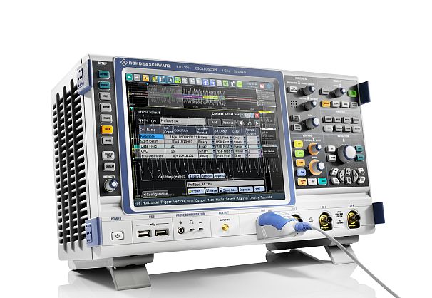
Understanding zone triggering technology enables users to determine when it can be effective and when it isn’t a good choice. How does zone triggering work? Well, it’s pretty simple. Users graphically draw one or more zones on the oscilloscope display as shown in Figure 1. Each zone can be parameterized with a “must intersect” or a “must not intersect” condition. With each new oscilloscope acquisition, the scope looks through the acquired record. If the acquisition matches the zone conditions set by the user, the scope displays the data. If the acquisition does not meet the zone condition, the scope discards the data. As a result, only acquisitions that meet user-specified zone conditions are displayed on the oscilloscope.

Figure 1: Zone triggering complements traditional hardware-based scope triggering by allowing users to graphically draw one or more zones where a signal should intersect or should not intersect. The oscilloscope only displays acquisitions that meet the zone conditions and discards other acquisitions. In this example, the R&S RTO2000 uses four zones to isolate a 0, 1, 0, 1 pattern.
Zone triggering is typically set up as a second stage in a trigger and follows a traditional hardware-based trigger condition such as an edge trigger. This allows users to use a traditional trigger condition to narrow down event types, and then use the zone trigger to add greater specificity.
- Why use it?
Zone triggering allows the user to graphically specify conditions that the trigger must meet. From a usability perspective, this often is simpler than determining how to accomplish the same goal using a traditional hardware-based trigger condition. More often though, zone triggering allows users to isolate specific events that would be impossible to trigger on using traditional trigger selections. Zone triggering was invented to help engineers isolate events that a traditional hardware-based trigger can’t isolate.
What are some examples? Double data rate (DDR) memory read and write cycles include wave shapes that vary slightly. Separating read versus write cycles is impossible to do using a traditional oscilloscope trigger, but very easy to do using zone triggering. The user simply draws a small square on the part of the waveform that varies between a read and a write cycle and then can specify “must intersect” or “must not intersect” to have the scope only display the desired cycles. Zone triggering can be used to display acquisitions that have a non-monotonic edge. Zone triggering can be used to specify a sequential pattern of 1’s and 0’s by drawing a zone in each sequential clock period. Zone triggering can be used to graphically isolate serial bus packets. For example, a user can draw a zone in an area where USB transmits data packets and only display data packets.
- What sources can be used with zone triggering?
Traditional oscilloscope hardware-based triggers operate exclusively on scope analog channels or digital channels. As zone triggering is a post-acquisition algorithm, from a technical perspective the technology can utilize a wider range of sources. Recent advances in zone triggering allow users to select math as a source. A user can specify a zone that operates on a math equation, or an FFT. This advancement provides unique capabilities not found in hardware-based triggering circuits nor in earlier generations of zone triggering technology. For example, in the frequency domain a user can use zone triggering to isolate all events where a sideband exceeds a specified power level. Or, in the time domain where a user has connected a current probe and a voltage probe and multiplies to get power, the user can have the scope on display events where power is greater than a desired value. The addition of math as a source for zone triggering makes zone triggering incredibly powerful and allows it to be used as shown in Figure 2 and Figure 3.

Figure 2: Recent innovations in zone triggering allow the technology to be used for math functions in addition to scope channels. In this example, the R&S RTO2000 has two single-ended passive probes connected to D- and D+ USB signals shown in the upper diagram. Zone triggering has been set to work on a math function that combines the two single-ended signals into a differential signal shown in the lower diagram.

Figure 3: In this example, the user has set a zone trigger in the frequency domain on the R&S RTO2000. The oscilloscope will capture and display only acquisitions where the sidebands exceed a certain power level.
- What are the tradeoffs?
Most technology innovation has tradeoffs, and zone triggering is not excluded. Remember that zone triggering is a postprocessing technique. This results in two undesired consequences. The additional postprocessing needs to slow down the overall update rate of the scope. It’s not uncommon to see zone triggering reduce update rates by a factor of 100. This may cause the scope controls to feel more sluggish. More importantly, the additional processing requirements will result in increased blind time between scope acquisitions. This renders zone triggering effective only where signals are repetitive. The amount of time required to perform the required zone triggering processing will vary by vendor oscilloscope family and be heavily influenced by the amount of memory that is turned on, and the type and quantity of zone sources. In short, traditional hardware-based triggering is the only method to ensure capture of rare or non-repetitive events.
- How to evaluate across manufacturers?
If you are thinking about adding to an existing oscilloscope or evaluating zone triggering capabilities on a new oscilloscope, here are a few areas to consider for comparison. The zone triggering application typically is available on oscilloscopes that are several hundred megahertz in bandwidth or greater with sufficient processing capability. Check with your manufacturer to see which of their scopes supports zone triggering. For scopes that support zone triggering, almost all oscilloscope demo units will have the option enabled for evaluation. For existing oscilloscopes where zone triggering is offered, vendors typically allow users to get a trial license.
One big difference users will find across oscilloscope manufacturer zone triggering applications is the sources on which the zones operate. All zone triggering applications allow the user to specify an analog channel as a zone source. A smaller fraction of manufacturers allow zones to be applied to math functions. Math is commonly used for power analysis and for differential signals. Hence, zone triggering on math sources can be extremely valuable, as traditional hardware triggers can’t trigger on math. Does the zone triggering application you are evaluating support zone triggering on FFTs. Oscilloscope hardware triggers operate on time domain signals and can’t be used in the frequency domain. Zone triggering is the only way for an oscilloscope to trigger in the frequency domain.
Another difference will be the amount of processing time that each manufacturer takes when zone triggering is enabled. While it’s possible to measure update rate with a specific zone triggering configuration, all scopes are slowed down when zone triggering is enabled. Zone triggers can miss infrequent events. A hardware-based trigger is the only method to guarantee that the scope won’t miss a trigger event. For this reason, impact on update rate speed might not be significant as a comparison metric, unless it is at the point where controls are sluggish or viewing is significantly impaired due to slow update rate.
A number of other attributes will vary across oscilloscope vendors. Some vendors will allow users to exclusively draw rectangles as zone shapes while others will allow users to draw arbitrary zone shapes. While rectangles are sufficient for a number of applications, the ability to create an arbitrary shape can help isolate events that require more precision. How easy is it to modify the zone size, shape, source and type? Experiment adding and removing zones on each scope you are evaluating. Users tend to add and/or remove zones more frequently than they originally anticipate.
Zone triggering is an oscilloscope technology that complements traditional oscilloscope triggering and is growing in popularity. For users who haven’t previously invested in zone triggering applications, the technology continues to evolve and can help isolate events where traditionally hardware-based triggers fall short. Recent advances include the ability to apply zone conditions to math functions and FFT views. For repetitive signals, zone triggering makes an excellent complement as a second stage to traditional oscilloscope triggering technology.
Author: Joel Woodward, Rohde & Schwarz USA
Joel Woodward is employed by Rohde & Schwarz as a strategic planner for oscilloscopes. He has worked in the test and measurement industry for 27 years. Joel holds a degree in electrical and computer engineering from Brigham Young University, an MBA from Regis University, has completed course work at the Harvard Business School and holds an FPGA debug patent. His outside interests include digital photography and hiking in national parks.