
- In modern communication systems, information is digitised, coded to logic levels “1” and “0” and often further encoded into complex modulation schemes such as Pulse Amplitude Modulation (PAM) or Quadrature Amplitude Modulation (QAM). Integrity of the information at the received end can be critical, so it is essential that any errors can be avoided, and if not, repaired.
- When major errors occur in the transmitted data, such as where significant parts of the data is missing, or the frame looks very different from what is expected, Equipment Management Systems can determine a problem and manage it accordingly. But, minor errors, where only a small number of bits in the frame are corrupt, the data looks the same to the system and errors are therefore not so easily spotted. One single error can be enough to cause the meaning of the message to be drastically altered, but the system has no way of knowing it.
- This article, offered by Anritsu, introduces Forward Error Correction (FEC), a function capable of correcting errors in the received data, how it came about and some of the benefits and trade-offs in its operation.
Andy Cole, Anritsu EMEA

The diagram shows the voltage transition from logic “0” to logic “1”, then back to logic “0”. At a voltage level somewhere between the logic 0 and 1 state is a threshold, about which an electronic decision is made whether it should be a “0” or “1” at that point in the data stream. If the amplitude of the bit is not sufficiently above or below the threshold, an error in interpreting the data can result. Attenuation is the signal past, Jitter and Noise in the system can easily result in errors.
Parity Bits
Parity Bits provide one of the simplest ways to check if a received block of data has a bit error by counting the number of logic “1” and sending a parity bit along with the data.
Parity can be odd or even, but in this case let’s assume odd parity. If we send a data word 11101001 we count five 1s. Five being an odd number agrees with odd parity, so we allocate a “0” parity bit to follow the data. If the count of logic 1s had been even, disagreeing with odd parity, then we would allocate a “1” parity bit to follow the data.
At the receiver we simply apply the same calculation to the data word and check to see if the parity bit at the received end matches the parity bit sent.
Since bits are binary, having only two states, a single bit error will flip the parity bit from a “0” to “1” and vice versa. However, if two or any even number of errors occur in the word, the parity calculation cancels. So parity is only useful where errors are very unlikely, and, if they occur at all, only one bit is likely to be received in error. If the data is critical, the only course of action when parity fails is to have the data retransmitted. It would be much more useful, when identifying an error, we had some way to correct it. FEC does exactly that.
Forward Error Correction
Forward Error Correction (FEC) is a process where the results of algorithms are sent as additional information along with the data from the transmit end. By repeating the same algorithms at the far end, the receiver has the ability to detect errors at the single bit level and correct them (correctable errors) without the need to have the data retransmitted.
Hamming Code, probably the first form of FEC, was first invented by Richard Hamming as long ago as 1950. While working at Bell Laboratories, he was frustrated with frequent errors in the punch cards, used to record and transfer data at the time, so devised a coded method to identify and correct errors and so avoid the need to have the cards reproduced and resent.
In this example an 8 bit word is sent followed by five check bits. If an error occurs to one of the bits, the error can be detected and better still corrected. Assume that we want to transmit a data word 11101001.
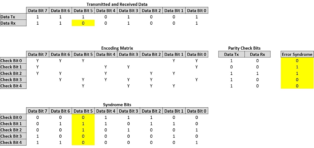
First five check bits that will be added to the data word are calculated. Count the number of “1s” in the data stream that correspond to the “Y”s in the “Check Bit 0” row of the “Encoding Matrix”, to calculate the value of the first “Parity Check Bit”. Repeat the same process for rows “Check Bit 1” to “Check Bit 4”, to calculate the remaining four Parity Check Bits for “Data Tx”. In the example above the Check Bits are 10111, so 1110100110111 is transmitted.
The receiver carries out the same check on the eight bit word and compares the two series of Parity Check Bits, each bit at a time. If the Parity Check Bits are the same, it resolves a “1”, if the values differ a “0”. If the result is all 1s, the data is error free, anything else and we know there is an error. This is known as a Syndrome, often referred to as Error Syndrome, Syndrome Code, etc.
In the example above “Data Bit 5” has been received in error, a “0” instead of “1”, resulting in an Error Syndrome 01100. The “Syndrome Bits” matrix, which corresponds to the “Encoding Matrix” confirms that the error occurs in “Data Bit 5”. The system can now revert its state and the data is corrected.
Over the years FEC has continued to be developed to the point now where many errored bits in a long stream of data can be successfully detected and corrected at the receiver, without the need to have the data retransmitted.
Reed Solomon FEC (RS-FEC)
G.709 defines Reed Solomon FEC (RS-FEC) for modern Optical Transport Network (OTN) systems. The standard also allows equipment vendors to use additional FEC to further improve the effectiveness of error correction.
Sometimes referred to as RS (255,239) code, RS-FEC for OTN manages and corrects data errors for an information block of 239 symbols, each symbol having 8 bits. A further 16 check symbols of 8 bits each are used to transmit the result of the RS-FEC algorithms, making the total transmitted data block size of 255 symbols. Approximately 6% of the data transmitted is FEC overhead and you could ask, why when bandwidth is at such a premium how it can be efficient to commit such a high resource to error correction.
To assure error free transmission without FEC, it is necessary to maintain a good Signal to Noise Ratio (SNR), where the amplitude of the signal is well above the electrical noise (the Noise Floor) of the system. The more the signal attenuates, the closer it gets to the noise, increasing the probability that the noise will cause errors in the data. Maintaining the optical power at a level necessary to avoid errors, might require amplifying the signal. This could mean converting the signal to electrical, amplifying it and retransmitting as an optical signal again, which all adds to cost and latency.
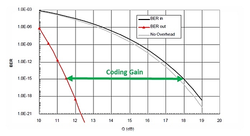
However, because FEC is able to correct a certain number of errored bits, we can accept a reduction in the signal level and allow it to drop closer to the noise, as long as we stay within the limits of correctable errors. This permitted reduction in SNR is called the Coding Gain, defined as the difference in Input SNR for a given Output BER. The Input SNR is measured either as Q Factor or as Eb/N0 (bit energy noise power spectral density ratio).
The graph below shows that a system requiring a BER of 10-15 RS-FEC delivers a Coding Gain of approximately 6.2dB. But, when additional FEC from equipment vendors is deployed, Coding Gain approaching 12dB can be achieved.
Coding Gain provides several benefits that improve efficiency network equipment that results in better use of bandwidth. Some of the benefits are:
- Ability to lower the transmission power and maintain information integrity across the same span
- The ability to transmit signals further without the need to amplify or retransmit improving the efficient use of network equipment, power and improve latency.
- Reductions in the need for network equipment and power resulting in savings through the use of less environmental control such as, buildings, air conditioning, etc.
- Where the number of DWDM channels is limited by the aggregate power, the ability to reduce the transmission power allows for more channels before the maximum aggregate power is reached.
Testing for FEC
FEC is heavily relied in maintaining the integrity of data in modern communication systems to realise the benefits and improvements in efficient and effective use of network equipment, bandwidth and environmental considerations. FEC must be robust and reliable, and it is therefore necessary to test that FEC is working as specified by G.709 and in the case of any additional FEC, by the more stringent specification from the equipment vendor.
The Network Master Pro from Anritsu supports the needs of a complete and professional commissioning test regime. It characterises Network Performance and tests the effectiveness of the FEC deployed.
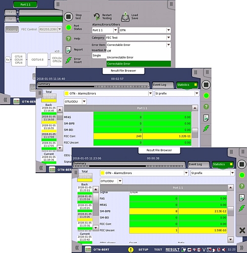
The image shows how FEC errors can be stimulated by the Network Master Pro and how easy to read results screens give statistical information of how the network equipment manages Correctable and Un-correctable FEC errors.
In conclusion, despite a seemingly heavy 6% overhead requirement, the benefits of FEC outweigh the cost. A reduction in the need for optical channel power through a coding gain of 6.2dB for RS-FEC and a possible 12dB when vendor specific FEC is added, results in power savings through reduced amplification and environmental control, and making better use of spectrum lighting more WDM channels to gain bandwidth. But there is a fine balance between maintaining the integrity of the information and catastrophic errors. Therefore the need to properly test the operation of FEC, by stimulating errors to ensure errors are corrected and guarantee the required BER is achieved is more important now than it ever has been.