
- Testing of energy storage systems ranges from small batteries used in portable devices, to larger batteries in electric vehicles, to batteries used in high-power backup power systems for stationary equipment.
- Tektronix Keithley offers test solutions for all situations during all phases of battery manufacturing, including high-precision resistance, insulation, and voltage and current measurements while collecting data from multiple test points.
- Andrea Vinci, technical marketing manager at Tektronix, explains why its solutions are particularly suited to the needs of automatic test system (ATE) integrators for electric vehicle OEMs.
Safety, performance, and system management
The “battery testing” context can be really wide, spanning from the characterization of the smallest possible cell in portable devices to the large vehicles’ batteries operating at 1000V or even higher.
The Battery System is of paramount importance for electrified mobility. Nowadays, lithium-ion batteries are among the most common used types in electric vehicles due to their high energy
and power density, having the technology achieved also a decently long enough lifespan.
There are different nomenclatures and naming used for the “batteries” that depend on the market context: in Automotive, for instance, depending on the state of integration in the vehicle, the EV battery as a DUT (device under test) and the test procedures to it related can differ if you refer to cells manufacturing, modules or packs manufacturing.
The cell is generally the single electrochemical device, the individual storage unit typically ranging not more than 5V maximum. The module is composed by several cells connected and some other electronics to control the entire system. A module is somehow packaged, so tests generally involve the whole thing as a single element. A pack is a larger element composed by several modules, again connected by some wiring and with more sophisticated control and communication electronics on board to communicate with other processing units like in the case of vehicles.
As said, testing cells is not the same as testing modules, or testing packs, and test setup can vary at each stage of the manufacturing value chain. Tests can finally differ by the test methodology used too, as in the case of impedance measurement for instance.
We as Tektronix Keithley are supplying solutions for test system designers covering electrical tests, concentrating on wherever a potential (voltage), a current and a resistance measurement is needed in complex ATEs for system integration testing in both battery manufacturing (e.g. cells, modules and pack assembly lines) as well as final application integration (e.g. Automotive Battery Management System – BMS and battery pack integration).
Tests generally refer to three main areas: safety testing, critical for a system built as a combination of several cells arranged in series/parallel topology to deliver a higher power density, performance testing of the battery cell/module/pack, closely related to the number of charging/discharging cycles, running time and temperature, and management testing when performance optimization and EOL test validation is key.
Example 1: Busbar Weld Impedance Safety Test Workstation in Battery Packs Manufacturing
The multiple cells composing a battery module are connected in parallel or series to achieve the desired voltage output. All cells are laser welded to a busbar, a long conductor that is isolated from ground and is responsible for carrying high current for distribution of power from the battery. The VSH-Busbar weld impedance test characterizes the impedance of the weld. Small resistances in the weld can generate enough heat to degrade the batteries and lead to early failures or unsafe operating conditions. By measuring the resistance before testing the battery operation, defective modules can be quickly removed from the line.

Measuring the impedance of the weld involves sourcing a current across the weld and measuring the voltage to calculate the resistance. Test execution speed and measurement accuracy are the two most important considerations when measuring the weld impedance. This can be done using Source Measure Units (SMUs) like the Keithley models 2460 or 2461 and either the model 3706A System Switch and Multimeter or the model DAQ6510 Data Acquisition and Logging Multimeter System.
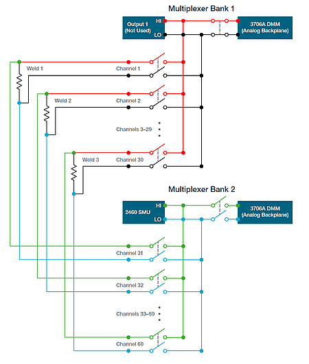
The model 2460 and 2461 SMUs are capable of sourcing up to 7A for battery systems requiring high current. The impedance of the weld can be as small as a few milliohms, therefore it’s important to use a sensitive enough meter to measure very small voltages. The model 3706A features a 7.5-digit digital multimeter (DMM) and can measure 10s of nanovolts on the 100mV range. Since a battery pack could have close to 80 welds on one busbar, we support mainframes with configurable slots for multi-channel plug in modules eliminating the need of rewiring. The process of closing each channel to measure is obviously automated for speed and efficiency.
Example 2: Internal Resistance Measurement and Open Circuit Voltage in Cell performance testing
The performance of a battery and its efficiency during charge and discharge process can be evaluated in few different ways and looking at several indicators. The battery internal resistance characterization is one of them, and it basically means accurately characterizing its changes under several charge/discharge current rates, State of Charge (SoC), temperature, and other aging indicators.
Open Circuit Voltage (or OCV) is the voltage measured at the terminals of the battery after enough rest time (called relaxation sometimes), and it is a key measurement for Li-Ion battery cells.
OCV also varies mostly according to battery state of charge (SOC) and at a less extent according to the temperature, and it can be used to create a battery equivalent model, therefore, to design a Battery Management System (BMS) so not only to evaluate/assess battery specs and condition.
Internal resistance in the battery accounts for the voltage drop across battery’s terminals when a load is connected compared to no-load voltage and can be derived from OCV measurements.
OCV is generally not just “a measurement”, but a set of measurements. In fact we call it the “OCV characterization of the battery”, and we trace an exhaustive analysis derived from a curve on a State-of-Charge (SoC) versus OCV plane.
To trace this curve, you need to bring the battery to specific states of charge, typically by charging or discharging current in a pulsed way using a smart source/load, then wait for some settlement time (called “relaxation”), and then measure the open-circuit potential at the electrodes.
A Keithley SMU like the 2460 or the 2461(with 10A pulse capability and digitizers) is a perfect solution to perform this test. In fact, it can either source or sink the cell current in a controlled way while measuring the cell current and voltage with a 4-wire (Kelvin) connection with contact check. All this easily automated and controlled by a programmed embedded microprocessor.
The accuracy of the voltage measurement in OCV is a discriminating factor for the choice of the instrument. In some cases, the typical 6 ½ digits measurement resolution, the thermal stability but mostly the accuracy of a SMU can be considered not sufficient.
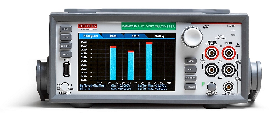
For this reason, some test setups involve a special digital multimeter, the Keithley DMM7510, that became a standard in Li-Ion battery cell testing. Its low noise 32 bits A-D converter allow 7 ½ digit resolution and metrology grade accuracy.
Example 3: BMS testing and a special case for collision switch detection
A Battery Management System (or BMS) is a specific element in charge of performing critical battery functions control like cell monitoring, cell balancing, charge and discharge control, safety control and communications with external units. Several ATE designers work to squeeze into a compact and reliable platform all the needed test units to control the interaction between the BMS and the battery.
These ATE for validation are typically modular elements, with items from multiple vendors combined to operate together as a system. The system needs to track and log multiple input signals coming from the battery and the BMS. The sensing units and the I/O – communication stage is indeed critical and must be implemented for proper screening. In some cases, the choice of the individual instruments to compose the system is partially driven by the test management software environment, but in general system integrators prefer to design custom solutions based on OEMs requirements, which are independent from a specific environment granting an interchangeable and fast execution in parallel of several automated validation test systems.
To validate the BMS prior to the real battery system interaction you may need to simulate the battery pack voltage. This means to control a precise 1000V (or more) voltage source or even the simulation of hundreds of individual cell voltages. Environmental stress chamber is another key sub element to include for temperature and test atmosphere control. From a SMU perspective, Keithley support with model 2470 capable of exceeding 1kV test capability.
Aside the specific portfolio of data loggers and acquisition switch cards like the DAQ6510 for instance, we will focus now on the need of voltage and current pulsers chosen for specific design of test setup for BMS reaction to low energy collision during a DC fast charge.
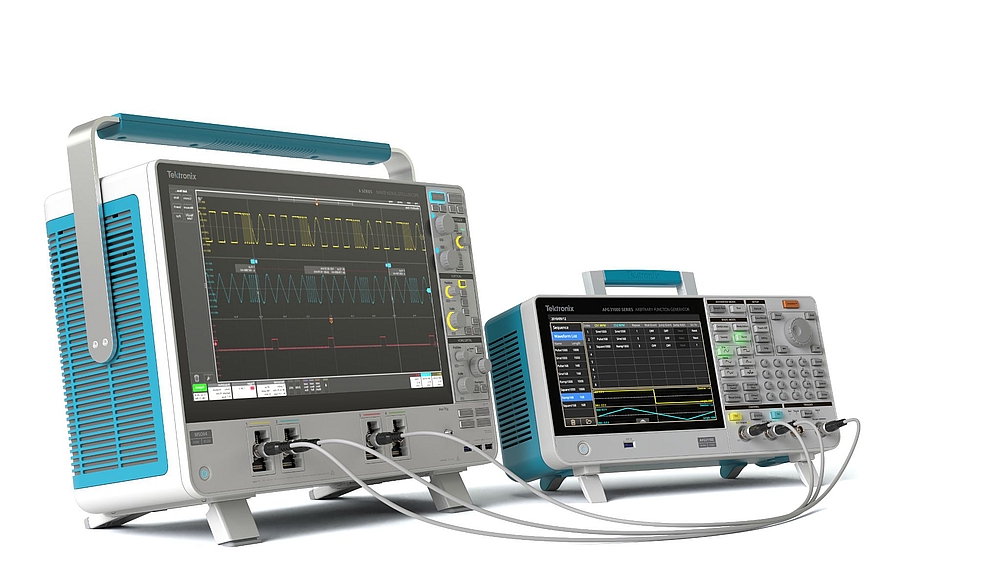
Let’s consider the case of a vehicle plugged to a DC charger in a parking lot that suffers a low speed collision. How does the BMS will react? How to exclude critical faults like on isolation? The collision signal to the BMS may be a voltage pulse or a current pulse, depending on the actual situation. Regardless of the type, the signal is required to be clear and stable enough to resist interference. We also supply solutions with our AFGs to simulate error frames in the CAN bus messages communications in order to recreate potential fault situations and test the system robustness against it.
- About the author
Andrea is a Technical Marketing Manager at Tektronix, responsible for the Keithley Instruments Portfolio in EMEA. He received his Electronics Engineering MSc from University of Padova in 2000, contributing on I.V.I. standard for T&M. He then spent over a decade in design and technical management roles across multiple corporates. He joined Tektronix in 2011 as Field Applications Engineer first, then as Sales Account Manager in Italy and later as Business Developer across the EMEA region, focusing on new Semiconductors and Power Conversion applications. He lives nearby Venice, Italy where he loves to play with his crazy Golden Retriever.