
- Mobile fronthaul is evolving with new technologies where optical fibre is the preferred choice for the centralised radio access network, with millimetre-wave transmission being an alternative where installing fibre is not practicable.
- The CPRI specification addresses the key internal interface of radio base stations between the radio equipment control and radio equipment, but this relies on a robust, reliable and efficient fronthaul network.
- With 80% of CPRI turn-up issues caused by Layer 1 faults, it is recommended that inspection and testing is carried out during the network build-up process to ensure correct installation and operation before connecting and operating the baseband unit.
- A test tool such as the Anritsu Network Master, which incorporates capabilities in both the physical layer and CPRI operation, is essential for the building, commissioning and troubleshooting of C-RAN systems.
Author : Andy Cole, Anritsu
Mobile networks are already becoming overstretched in their ability to provide the capacity required, and as people’s expectations rise – in terms of the media available and the number of mobile devices they want to connect – the need for more capacity will grow even further. While modulation schemes can serve to maximise the efficient use of available bandwidth, still more network infrastructure must be provided to support the capacity required. The Internet of Things (IoT), where everyday household devices are connected to the internet, will only serve to compound the issue.
In a mobile network, a base transceiver station (BTS), or more recently a baseband unit (BBU), acts as the interface between the global fixed network and a wireless access network. Its job is to convert media data to mobile data traffic so that it can be transmitted over the air interface in an RF signal and vice versa for mobile to media data.
Mobile backhaul is a term used to describe the connection between the BTS/BBU and the fixed network, supported by fibre-optic technologies like SDH/Sonet, Synchronous Ethernet and OTN, where bandwidth and synchronicity can be guaranteed.
Fronthaul, on the other hand, is the term used to describe the process of sending mobile RF data traffic as a digitised signal between the BTS/BBU and the radio equipment for “over the air” transmission to and from the mobile device. Fronthaul technology is evolving to support an ever-increasing need for bandwidth as well as efficient and robust communication, while at the same time reducing power consumption: a major cost factor in mobile installations.
In older mobile fronthaul networks, which rely on transmission over coaxial cables between a BTS and a passive antenna, bandwidths can be extremely limited. The BTS has to be close to the radio equipment – generally at the base of the tower – which means that power and environmental control have to be provided at each and every cell site.
Fig.1 shows how coaxial and power cables link the BTS to a masthead amplifier, which is then connected to a passive antenna. Losses over the coaxial cable limit the cable length, and high power levels need to be transmitted between the BTS and the masthead amplifier to overcome signal degradation.
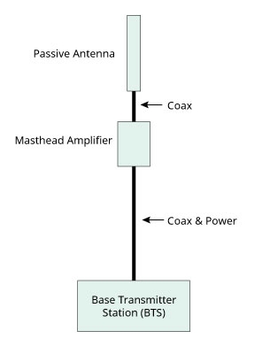
Fig.1. The BTS connects to a masthead amplifier via coaxial and power cable, which is then connected to a passive antenna
New Services
Mobile operators have to meet the growing need to provide capacity and coverage to support the increasing variety of devices communicating over their networks. Some services, such as eCall – a feature soon to be made mandatory to all automotive manufacturers, where a vehicle can detect that it has been in a traffic incident and automatically alert the necessary emergency services – will rely on guaranteed coverage and network availability.
This requirement is only made possible by a reduction in the cell size coupled with the use of complex modulation schemes to maximise the efficiency of the available bandwidth. Fortunately, technology is evolving: both in the communication techniques used between the antenna and the mobile device and in the fronthaul area, where these enhancements have to be considered along with cost and environmental considerations.
This process involves two stages of evolution, based on the use of fibre as a much more efficient carrier than costly and troublesome coaxial cable for high-quality low-loss data transmission:
- First, the use of fibre between the BBU and a remote radio head, followed by a link to a passive antenna via a short length of coaxial cable.
- Secondly, a more recent solution involving fibre and power being provided directly to radio equipment incorporating an active antenna, totally eliminating the need to use coaxial cable.

Correctly installed optical fibres support low-loss, reliable and robust connectivity over far greater distances than coaxial installations, so that there is no need to site a BTS close to the radio equipment. A BBU can be sited some distance – maybe up to 40km – away from the radio equipment, so that BBUs can be housed together in a centralised location. This leads to much more efficient use of power because fewer sites need to be supported. Maintaining the network is also much easier as the management and test functions can be supported from the centralised location.
These newer networks employ a distributed antenna system (DAS) – also referred to as a centralised radio access network (C-RAN) or a cloud radio access network.
Transmission over the air provides a line-of-sight communications link. Challenges can result from the external environment, where the local geography or buildings might block the transmission path, or in buildings, where wall dividers and other infrastructure features can cause obstructions. With the advent of 4G and (currently in discussion) 5G networks, where huge antenna arrays to support technologies such as massive MIMO (multiple-input/multiple-output) might be used, these fronthaul networks will become vast and ever more complicated.
It is generally agreed that the preferred method to address these challenges is to use optical fibre throughout the installation, but, where it is impracticable to deploy fibre, millimetre-wave transmission over short distances can provide the answer.
The CPRI Standard Interface
A method had to be devised to communicate the mobile data traffic throughout the radio access network, regardless of its complexity, while maintaining the signal integrity, which relies heavily on timing (synchronisation).
The Common Public Radio Interface (CPRI) specification describes a co-operative industry effort aimed at defining a publically available specification for the key internal interface of radio base stations between the radio equipment control and the radio equipment itself. The mobile data traffic is carried as I/Q (in-phase and quadrature) data in a user plane, as shown in Fig.2. In addition to the user plane, the CPRI interface incorporates a control and management plane and – most importantly – synchronisation.

Fig.2. Schematic illustration of the layers in the CPRI standard interface
The interface has two main layers:
- Layer 1 is the physical layer and covers both electrical and optical transmission using time division multiplexing (TDM).
- Layer 2 supports Layer 1 in-band protocol, where alarms and errors can be analysed to support troubleshooting the network. HDLC (high-level data-link control) provides protocols for transmitting data between points in the network and acknowledges receipt. Mobile data traffic is carried as I/Q data, and vendor-specific information provides for further management and control, redundancy etc.
The CPRI standard supports various types of network topology to provide for flexibility in network design.
Network Reliability
An optical fibre network will provide many years of reliable service if it is properly installed and protected. Each fibre end should be prepared, spliced or connected employing best industry standard practices. Where connectors are used, fibre end faces must be cleaned and inspected on both sides of the joint. Any dirt or scratches can cause devastating failure now, or sometime in the future. Time spent on getting these details right will pay off over time, as the cost of network failures in terms of fixing the problem, lost revenues until the link is fixed and potential penalties due to loss of service can very soon add up.
Once the network is completed it is critical to test the integrity and continuity of the installation. Care needs to be taken when installing optical fibre to make sure that the joints are properly made and that the installation is free from macro bends and other unwanted events. Test equipment such as Anritsu’s Network Master test (Fig.3) includes a FTTA (fibre to the antenna) application for this purpose (Fig.4), allowing individual faults to be identified for a speedy fix.


Fig.3. The Anritsu Network Master test equipment

Fig.4. The Fibre Visualiser identifies individual faults as an aid to speedy troubleshooting
Turn-up testing with the Network Master allows the C-RAN installation to be fully tested prior to connecting to the BBU. The CPRI specification defines a sequence of common set of actions to be performed by two devices connected by a CPRI link. In normal operation the CPRI link is always on and both connected devices should be in either the operation state or the passive state. The Network Master assumes the role of either the radio equipment control or the radio equipment, switches the device under test either to the passive link state or the Operation state, and tests the link accordingly.
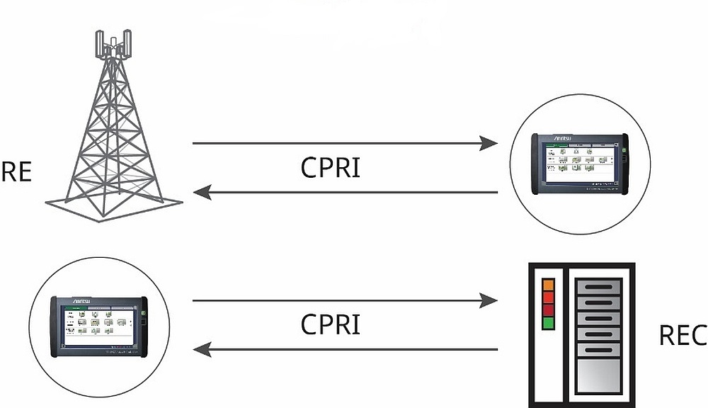
Fig.5 shows various mobile fronthaul configurations in which the test equipment can be used.

Test case 1: Testing the physical Link between the REC and RE before any of the equipment is connected

Test case 2: Testing network equipment (REC and RE) during installation or troubleshooting of the network

Test case 3: Connecting the tester in line or via test points allows the behaviour of the network to be monitored. This is especially useful for commissioning the network prior to sign-off, or for troubleshooting the network
The test equipment is used to confirm and verify that the RRH/RE is powered-up correctly, that the fibres are connected correctly, that the correct wavelength SFP/SFP+ modules are installed, and that that the SFP/SFP+ modules support the rate configured. It is also used in conjunction with a video inspection probe to monitor the optical connector condition and cleanliness.
It is also important to verify that the link has no excess loss from the RRH/RE to the BBU/REC, and that the RRH/RE can connect to the lower communications layers, including the C&M channels.