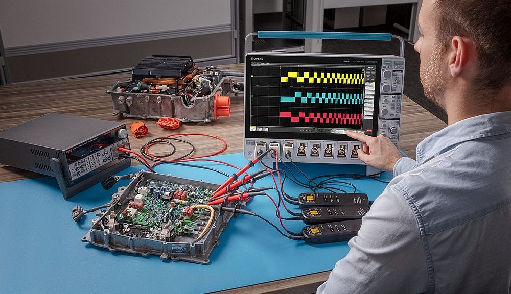
- This article explains how to make measurements with an oscilloscope using a software application dedicated to the analysis of drives, motors and power converters.
- This solution enables stable and accurate electrical measurements on the inputs, DC buses and outputs of variable-frequency drives, as well as measurements of motor mechanical parameters.
By Lee Morgan – Senior EMEA Technical Marketing Manager, Tektronix
Due to the pulse-width modulation on the output of motor drives, making stable measurements on these signals is challenging. Manually determining the right combination of filters and triggers to achieve stable waveforms is very difficult, yet this is a prerequisite for achieving consistent measurements.
In addition to measuring the output of the drive, measurements to evaluate the performance of the drive’s input stages, such as harmonics, power and power factor are also important. While exporting raw waveforms into a spreadsheet or other analysis software is possible, the process is time-consuming and requires care in designing calculations.
These measurements involve many connections to the device under test. Incorrect probing of the motor drive system and poor integrity of connections are common sources of errors in making motor drive measurements.
Mechanical measurements are also key and can be made using sensors. However, it may be difficult or impossible to get measurements in engineering units of speed, acceleration or torque without custom processing and scaling.
For these reasons getting a good view of a motor drive system with an oscilloscope requires careful setup, stable waveforms and robust measurement algorithms.
Vector Drives / Field-Oriented Control
The more advanced drives for AC induction motors and synchronous motors employ vector drive techniques. These drives are more flexible and efficient than scalar drives, but also more complex.
Vector drives have similarities with scalar ones in that they drive the motor with sinusoidal current, however vector drives provide smoother operation, quicker acceleration, and superior torque control. These control systems often use field-oriented control (FOC) and are significantly more complex than scalar drives.
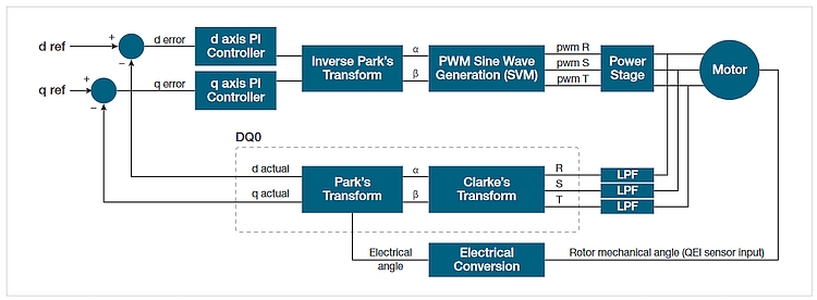
The vectors, D and Q are orthogonal vectors, whose magnitudes relate to the torque and magnetic flux within the motor.
The control system must measure the position of the rotor in order to synchronize the system. This is often done by using sensors such as Hall sensors or a quadrature encoder interface (QEI). (Sensorless systems are also used in which the control system uses the back-emf of the motor to determine rotor position.) The controller uses the Clarke and Park transform to calculate the magnitudes of D and Q, and then uses these values as setpoints for the control loop.
Making connections to a VFD system
Oscilloscope Probe Selection
Making power measurements on variable frequency drive systems requires voltage and current probes. When selecting oscilloscope voltage probes for motor drive measurements, it is important to consider:
• Motor drive measurements involve relatively high voltages. For example, the DC bus voltage in a 480 Vac three-phase motor drive is typically around 680 Vdc. Confirm the voltage rating at the probe tip and for the accessories used to connect the probe.
• Common-mode voltages can also be relatively high. That is, measurements are often “floating” relative to ground, so ground referenced probes may not be used. It is important to be sure signals are not floating more than the common-mode voltage rating of the probe.
• Most frequencies of interest are below 200 MHz, so probes with this bandwidth should be sufficient for most everyday measurements.
• Probes should cover a wide range of measurement tasks.
For these reasons, high-voltage differential probes are generally recommended as general-purpose voltage probes for power electronics inverter subsystem, drive input/output, and control system measurements.
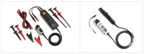
Note: Ground-referenced passive probes should not be used to measure phase-to-neutral voltages. The neutral terminal is probably not at ground potential, causing significant currents to flow through the probe and oscilloscope earth ground. This is dangerous and may result in shock or damage to the DUT or scope.
Oscilloscope Probe Setup
Before taking any power measurements, a few important steps must be taken. Current probes must be degaussed, and all probes should be de-skewed for accurate results.
It is important to perform a degauss procedure on current probes before taking measurements to remove any residual magnetization from the probe’s magnetic core. Residual magnetization will cause incorrect measurements. The procedure is typically performed by removing all conductors from the jaw of the current probe and initiating the procedure with a button press. Tektronix current probes, such as the TCP0030A, will automatically prompt you to perform a degauss procedure before use.
The deskew process corrects for various propagation delays between any two different scope channels, including the probe and probe cabling. This is important since phase relationships are critical for many of the measurements on VFD systems. The basic procedure is to provide channels with a synchronized signal and adjust delays for each channel to align them. A power measurements deskew fixture is available from Tektronix to help with this.
When connecting current probes, it is important to pay attention to the arrow on the probe. When the current probe is connected on the line side of the load, the arrow should point toward the load. If the current probe is connected on the return side of the load, the arrow should point away from the load.
Wiring Configurations
Often, both the input and output of VFDs use three phases. However, some VFDs used in commercial, residential, or automotive drive systems may be powered by single-phase AC or DC. In addition, 3-phase systems can be wired and modelled in two configurations: star (or wye) and delta. The wiring configuration determines the calculations used in power analysis, so it is important to understand and select the correct wiring configuration in order to get the expected results. These configurations apply to both the inputs and outputs of motor drives.
3-Phase Connections
Measuring 3-phase, 3-wire systems with 3 voltage channels and 3 current channels (3V3I)
Even though only two wattmeters are required to measure the total power in a three-wire system, there are advantages to using three wattmeters. The three-wattmeter configuration requires six oscilloscope channels: 3 voltages and 3 currents.
This 3V3I configuration provides individual phase-to-neutral voltages and the power in each individual phase, which is not available in the two-wattmeter configuration.
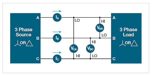
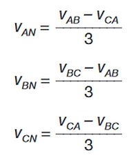
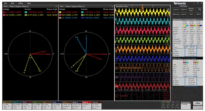
For 3-wire systems, measured with 3V3I, the IMDA software includes a setting to convert line-to-line (L-L) voltages to lineto-neutral (L-N) voltages. Although there is no physical neutral in this system, it is possible to determine the instantaneous line-to-neutral voltages from the instantaneous line-toline voltages.
This point-by-point LL-LN conversion expresses all voltages relative to a single reference and corrects the phase relationships between voltage and current for each phase. You can see the phase correction of the LL-LN conversion by noting the phase relationships on the phasor diagram with conversion turned on and off. Turning on LL-LN conversion allows instantaneous power calculations by multiplying phase-to-neutral voltages and phase currents. For example, we can find the total true power (STrPwr) being supplied to the load.![]()
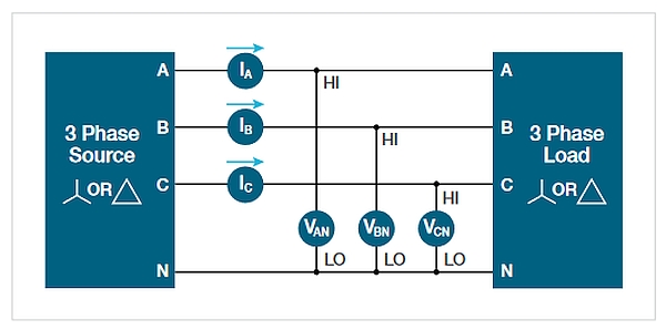
Measuring 3-phase, 4-wire systems with 3 voltage channels and 3 current channels (3V3I)
Three voltage channels and three current channels are required to measure the total power in a system that uses a neutral conductor between the line and the drive, or the drive and the motor. The voltages are all measured relative to the neutral. Phase to phase voltages can be accurately calculated from the phase-to-neutral voltage amplitudes and phases using vector mathematics. The total power, ΣTrPwr = P1 + P2 + P3.
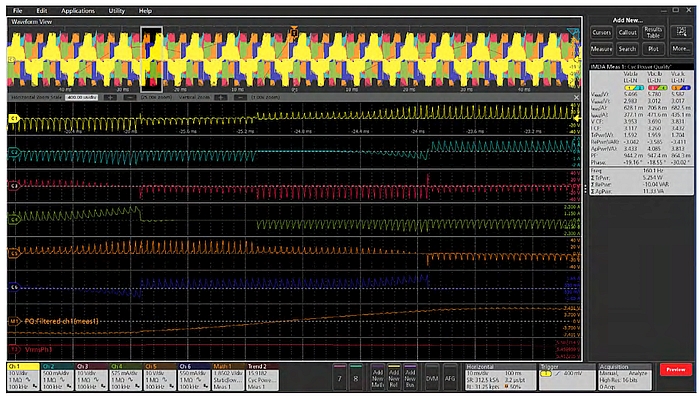
Making use of the oscilloscope built-in software that includes a 3-phase Autoset function that automatically configures voltages and current sources based on the selected wiring configuration is highly recommended. It will optimally set up the vertical, horizontal, acquisition, and trigger parameters on the oscilloscope and may be done on all active power measurements.
This greatly simplifies measurement setup, especially for PWM waveforms on the output of the VFD enabling for faster and more accurate measurements to take place.

