
- 5G ultra-reliable low latency communications (URLLC) is intended for services with stringent latency and availability requirements.
- Ultra-reliable low latency communications (URLLC) enabled 5G mobile networks must offer low latency, with minimal lost or messy arriving packets.
- The ITU-R (International Telecommunication Union Radiocommunications Division) specifies a one-way latency of 1 ms for the user plane.
- URLLC (ultra-reliable low latency communications) paves the way for various 5G wireless communication applications provided the required latency and reliability levels are met.
- Testing must be performed at all stages of the 5G network deployment, whether it is component testing, pre-deployment, commissioning or network maintenance.
- Anritsu presents in this article how these tests can be performed.
Author: Pavol Polacek, wireless technology specialist at Anritsu.
Ultra Reliable Low Latency Communications
5G Ultra Reliable Low Latency Communications (URLLC) are aimed at services with stringent requirements for latency and availability. 5G mobile networks supporting URLLC must provide low latency, with minimum packet loss or packets arriving out of order. The ITU-R specifies one-way latency of 1ms for the user plane [1].
To be more precise, we can define URLLC by decomposing the acronym and looking at the requirements:
• Ultra Reliability requirement ranging from between 99.99% for process monitoring to 99.999999% for industrial robots. This encompasses both transmission loss and packet reordering, with both needing to be as low as possible.
• The End-to-end Low Latency Communication requirements range from under 0.5ms to 50ms on the application layer and under 1ms on the 5G radio interface [2].
URLLC Use Cases
There are a number of applications that will make good use of URLLC [3] [4] [5]. Some of these are:
Augmented/Virtual Reality and Tactile interaction lets people experience an artificially created reality or provides additional information using a real world overlay. Already appeared in the entertainment industry, the technology is being developed for industrial applications like warehouse management and on site repairs, and could also cover critical applications such as augmented surgery.
Transportation will also benefit from URLLC as autonomous cars start to replace human drivers. Efficiency and safety will improve as vehicles and infrastructure make use of sophisticated sensors, artificial intelligence and near instantaneous communication. The main benefit of low latency is seen in remote driving and sensor sharing.
Electricity distribution is being improved by smart grids, which uses communication capabilities to achieve better power balancing and to detect and mitigate faults.
Motion control encompasses machine tools, printing and packaging machines. URLLC is expected to control moving and rotating parts of machinery in a synchronized manner, enabling high efficiency.
URLLC Standardisation
Early steps towards URLLC were taken by 3GPP with the first 5G release 15. The New Radio (NR) interface was defined with a latency of 1ms and a reliability of 99.999% [3]. However, the Non-Standalone Architecture (NSA) meant that the core network and the radio signalling must rely on LTE, failing to meet the URLLC end-to-end delay requirements.
With 3GPP release, 16 a new end-to-end 5G architecture is defined: Stand Alone (SA). With its own 5G core it can now operate without LTE and offers two important capabilities – network slicing and Mobile Edge Computing (MEC).
Technology Enablers of URLLC
End-to-end latency generally depends on the network performance and distance between the server and user equipment. Both were optimized to suit URLLC applications. Hereafter we look at technology enablers in 5G:
5G New Radio
The air interface has been optimized for low latency through flexible numerology, scheduling optimized for low latency or uplink grant-free transmission. Micro diversity, robust control channels and HARQ enhancements are importance in boosting reliability [3].
With a new numerology, the subcarrier spacing can be changed from 15kHz to 240kHz, with greater spacing resulting in shorter symbol duration and thus reduced scheduling intervals. Scheduling algorithms further reduce the transmission latency, thanks to the ability to schedule mini-slots. To avoid delays caused by requesting resources for transmission, uplink grant-fee transmission can be used.
Micro diversity uses multiple antennas on the receiver and transmitter side, creating separate spatial signal propagation paths and preventing single link failure. To ensure reliability, work was done to ensure robust Control Channels with low error rate – NR is introducing novel coding and using low Modulation and Coding Scheme (MCS) for their transmissions. The repetition mechanism HARQ is enhanced to reduce latency and increase reliability by pre-allocating resources for retransmissions.
Network Slicing
Network slicing is a crucial 5G functionality, allowing resources to be allocated on demand for users with different service requirements. Resources are flexibly partitioned and isolated from effects from other users, creating an end-to-end logical channel [2]. The QoS required by the user slices are configured on demand from the radio interface up to the core network.
For example, for the same user, 5G can create a high capacity video streaming slice without stringent latency constraints for enhanced Mobile Broadband (eMBB) services, and a low latency slice for URLLC service for robotic control. This capability can only work with the standalone (SA) architecture of the 5G core network.
Mobile Edge Computing
Mobile Edge Computing (MEC) greatly reduces latency and increases reliability by hosting the user applications at the “Edge-side” as part of the Cloud -Radio Access Network (C-RAN). The transmission delay is thus mainly due to the radio access. Hosting at the edge removes the need to go through core network, while lowering number of nodes on the data path also increases reliability [2].
Measuring End-to-End Latency in 5G Networks
All network components, ranging from wired or wireless transmission paths to nodes that add processing or queuing delay, add to the end-to-end latency. Understanding each of these latencies is important when selecting suitable components, but only the end-to-end latency shows us how these components work together. It is thus important to measure end-to-end latency of the network both before and after deployment.
Two setups are possible for end-to-end latency measurement, Near-end as shown in Figure 1 and far-end as shown in Figure 2.

With near-end measurement, the packets are sent from one port of the instrument into the network under test and routed back to the second port and simultaneously vice versa, to test the other direction. This is easier to set up, as both ends of the path end in one device and there is no need to synchronise two instruments. It is however harder to differentiate the downlink and uplink latency components, and determine how much they contribute to the overall latency.
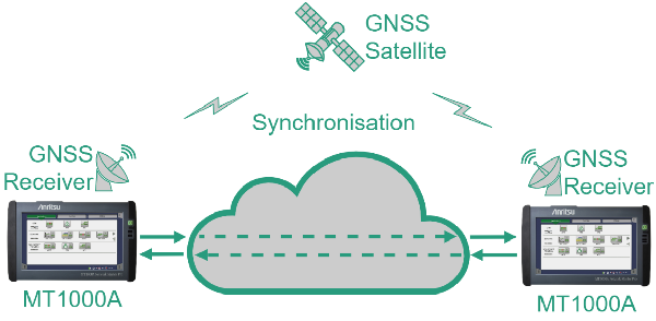
In the case of a far-end measurement, two instruments are placed at different locations and the packets are routed from one to the other. As two instruments are used, they must be synchronised by a high accuracy external clock, for example the timing signal that is part of a Global Navigation Satellite System (GNSS) signal. This provides greater flexibility, for example, one instrument can be co-located with a user device, while the second is sited at the server, so the instruments precisely measure both downlink and uplink directions. Another example are two instruments that can be placed inside moving vehicles – combined with mobile user equipment, latency can be measured while on the move.
Latency and Reliability Heatmap
To understand the performance of a network, latency and reliability needs to be measured at different locations. A heat map can then be created by coupling the performance, timestamp and location data, similar to wireless signal coverage maps that are widely used. These latency heat maps can be used to pinpoint potentially problematic locations and evaluate the actual network performance across an area.
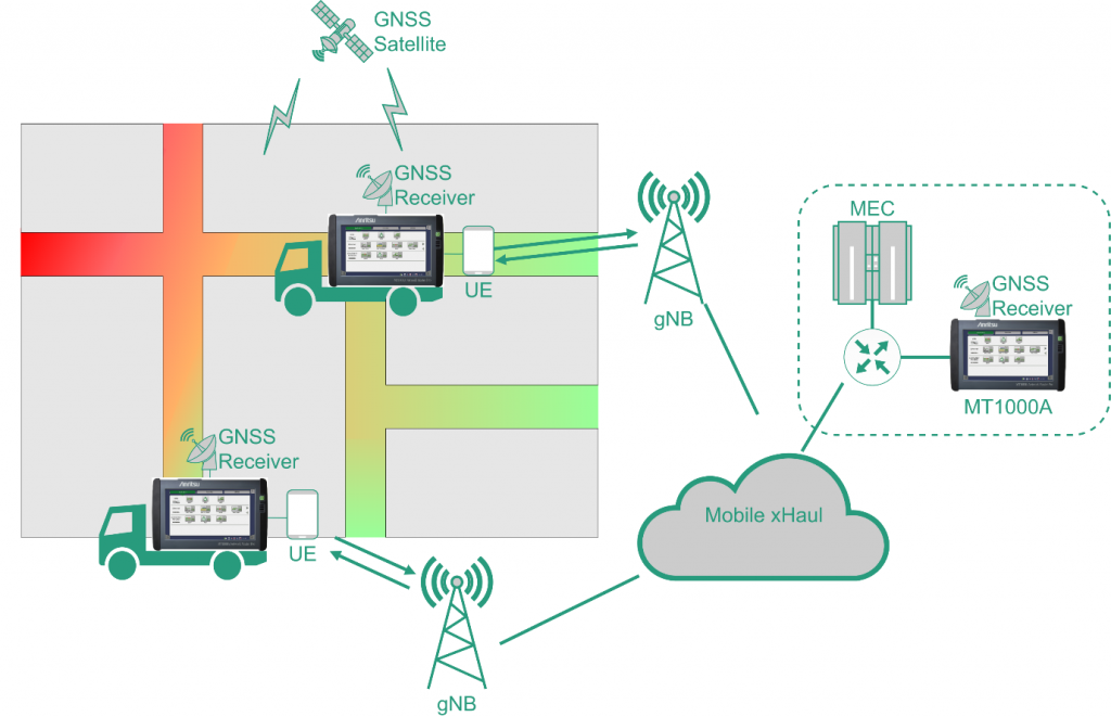
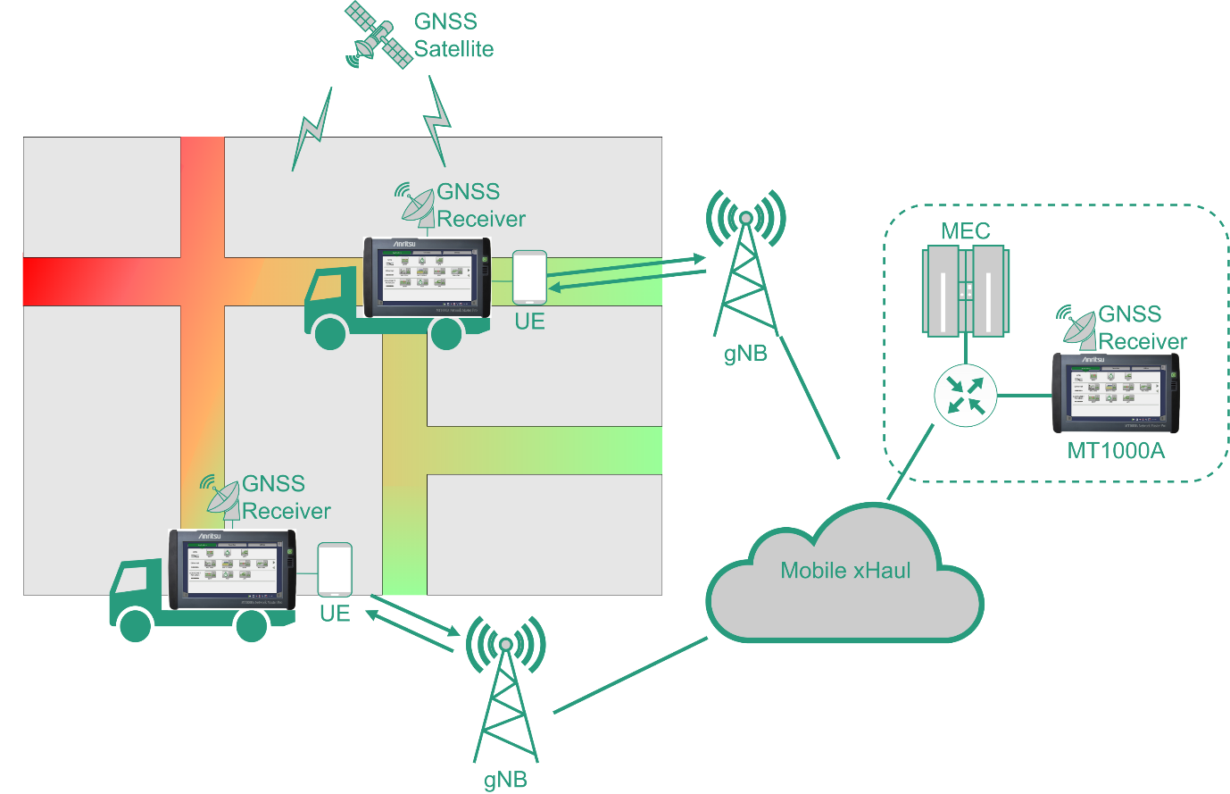
Measurement instruments are placed in vehicles driving in an area of interest, with another installed close to an MEC server, as shown Figure 3. The vehicles are equipped with GNSS receivers and a cellular UE, such as a 5G dongle or smartphone, providing connectivity to the 5G network. For example, by measuring the quality of the link between the MEC server and the vehicles, we can characterize the conditions under which MEC applications must function. Alternatively, by driving the vehicles in a platoon and measuring the link between them, we can determine if the connection quality is suitable for sharing sensor data between the vehicles.
MT1000A Network Master Pro
MT1000A [6] is the all-in-one field tester that can be used to evaluate the connection quality for emerging 5G URLLC networks. It can evaluate quality parameters like latency, jitter, pattern or sequence errors and packet loss. The MT1000A has a modular design, with different modules supporting combined 10G/100G Ethernet, OTN, SONET/SDH, OTDR, PTP and CPRI technologies. The software package is flexible and easy to use and allows the automation of testing.
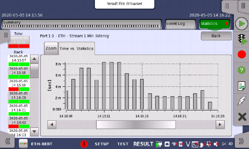
For testing URLLC latency, the MT1000A uses a custom application protocol – the end-to-end latency is calculated as the difference of the timestamp at the packet sending and the timestamp at the packet reception. The precision of the latency measurement is in the nanosecond to microsecond range as shown in Figure 4., depending on the underlying transport technology [7] [8]. This can be contrasted with ping, which is the traditional method for rough network latency measurement, limited to near-end measurement and lacks precision.
References
| [1] | ITU-R, “Report M.2411-0 – Minimum requirements related to technical performance for IMT-2020 radio interface(s),” ITU-R, 2017. |
| [2] | 5G Alliance for Connected Industries and Automation, “5G for Connected Industries and Automation,” ZVEI – German Electrical and Electronic Manufacturers’ Association, Frankfurt am Main, 2019. |
| [3] | Z. Li, H. Shariatmadari, B. Singh and M. A. Uusitalo, “5G URLLC: Design Challenges and System Concepts,” in 2018 15th International Symposium on Wireless Communication Systems (ISWCS), Lisbon, 2018. |
| [4] | 3GPP, 5G; Service requirements for next generation new services and markets (3GPP TS 22.261 version 15.8.0 Release 15), Sophia Antipolis Cedex: ETSI, 2019. |
| [5] | Next Generation Mobile Networks Alliance, “Verticals URLLC Use Cases and Requirements,” Next Generation Mobile Networks Alliance, 2019. |
| [6] | Anritsu, “MT1000A Introduction,” [Online]. Available: https://www.anritsu.com/en-us/test-measurement/products/mt1000a. [Accessed 27 2 2020]. |
| [7] | Anritsu, “Mobile Backhaul Test – Synchronous Ethernet Evaluation,” [Online]. Available: https://www.anritsu.com/en-US/test-measurement/support/downloads/application-notes/dwl010604. [Accessed 27 2 2020]. |
| [8] | Anritsu, “Faster Low-Latency 5G Mobile Networks,” [Online]. Available: https://www.anritsu.com/en-US/test-measurement/solutions/mt1000a-05/index. [Accessed 27 2 2020]. |