- Vector Network Analyzers (VNAs) are test instruments commonly used in the radio frequency (RF) field both in manufacturing and maintenance sites and in laboratories.
- These versatile instruments are used to characterise RF components, cables and antennas.
- To perform a measurement, a signal is transmitted to the Device Under Test (DUT) and the Vector Network Analyzer (VNA) measures the response of the device under test.
- Unlike scalar array analysers (SNAs), which only measure the amplitude of the return signal, VNAs also measure its phase. Thus, unlike an SNA, the VNA, a more sophisticated instrument, can check the phase shift as a function of frequency, as well as the gain of an amplifier over a given bandwidth.
- A vector network analyser is used to measure transmission parameters, crosstalk, distance to fault (DTF) and other parameters.
- A VNA can also be used to measure the directivity of an antenna or the properties of dielectric materials.
The SCPI and VISA libraries of the defined Application Programming Interfaces (APIs) and the control in C++, C#, Python or Matlab make it possible to implement customised measurement solutions beyond those provided by the instrument manufacturer.
By Pavol Polacek, Anritsu Wireless Specialist
Types of VNA
Bench top VNAs, like the Anritsu VectorStar, with an integrated display, a key and/or touch screen user interface, and the ability to run on-device control software, are easy-to-use and suitable for indoor applications such as R&D or device modelling. Potential drawbacks are their size, weight and relatively high price.
Another common type, tailored for field work, is the handheld battery powered VNA, like the Anritsu VNA Master. They also have an integrated display and control buttons, to enable them to be conveniently controlled while working off-site. Sometimes they can be combined with a spectrum analyser to produce an all-in-one field test solution. Due to their more specialist nature, they are not considered suitable for customized testing.
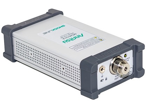
The third type of VNA, like the Anritsu Shockline family, does not have a display or control panel. Requiring an external PC with control software, they are more suitable for applications in manufacturing, military, aerospace, university environments or for field measurements when controlled from a tablet PC. A VNA without a display or control panel is considerably lighter, smaller, more rugged and cheaper, than an all-in-one bench top or handheld device.
Even though this third type seems less functional, it offers greater flexibility, due to its control interface, and the use of predefined APIs and custom specialized software.
Customized VNA Control using SCPI and VISA
VNAs can be controlled through different APIs/drivers, but the most common are the Standard Commands for Programmable Instruments (SCPI) and Virtual Instrument Software Architecture (VISA). These well established and well-defined APIs enable the creation of customized control software for VNAs. SCPI provides lower level access to VNA functions, with better speed and lower overhead, but requires the implementation of error checking and formatting. VISA, on the other hand, offers higher comfort to users by providing basic error checking and formatting but can be slower with higher overhead.
The flexibility of the VNA lies in its measurement capability and controlling software. The control software can be written using different programming languages like C++/C#/Python or Matlab, which can communicate with the VNA using GPIB, USB or Ethernet interfaces.
Common VNA measurements
VNAs are used to characterise many things including whole antenna assemblies and band pass filters. The most common usage however is the measurement of single RF or microwave components, such as cables, connectors or antennas, and also circuit boards during design. Thanks to the knowledge of the amplitude and phase characteristics of a device, a more complete picture of its behaviour can be painted. For example, one of the most important parameters of an amplifier is the gain over a given frequency band, but a non-linear variation of the phase in the whole bandwidth can cause the distortion of wide band signals, and, thus, this should carefully be evaluated.
A few examples of possible applications are:
Transmission Parameters
The transmission coefficient characterizes how the input signal changes by travelling through the DUT. If the amplitude of the transmitted voltage is lower than the amplitude of the input voltage, the DUT has insertion loss, and if the output is greater, the DUT has gain. The phase part of the measurement is called insertion phase. For each signal made up of multiple frequency components, it is important to know to what extent the DUT distorts and alters the shape of the signal. Knowing the parameters of the transmission through the DUT helps in the selection of the most suitable components, and the ability to compensate for the loss and distortion during transmission.
Crosstalk
Crosstalk is an undesired coupling effect that occurs as a consequence of conductors in close proximity to each other. It is measured as the relative percentage (or dB) of the signal from the originator line, that appears on the relative victim line. For example, during digital component design, the dimensions of printed circuit boards (PCB) tend to shrink and components are placed ever closer, so the connecting conductors can have capacitive or inductive coupling. Analogue crosstalk measurement can thus be surprisingly helpful during the design of digital components by mitigating its negative impact on the behaviour of the PCB.
Distance To Fault
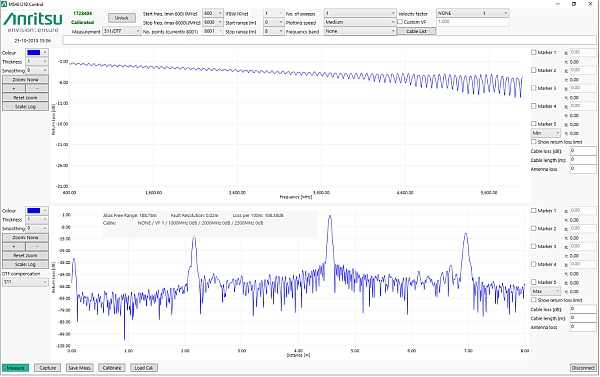
Distance To fault (DTF) is a measurement in the time domain rather than the more common frequency domain. It is used to find all the discontinuities of antenna assemblies or cables that may occur due to damage, loose connections, corrosion or the effects of aging. To obtain the distances to discontinuities, a sweep is performed over a set frequency range and all the resulting magnitude and phase information is stored. Next, the inverse Fast Fourier transform is used to convert the data to the time domain. Finally, the level of the reflected signal at each distance point is achieved by multiplying the time values on the x axis by the specific signal propagation velocity. With a wide frequency sweep, these faults can be pinpointed with considerably accuracy.
Custom Applications for VNA measurements
VNAs can cater for diverse customer requirements if the appropriate control software is available. These are a few examples that showcase the flexibility of VNAs and their potential for customization.
Lightweight Control Software for DTF Measurement
Field engineers often carry a tablet PC in order to diagnose, control or manage communication equipment. This tablet PC can also be used to run a lightweight software that can carry out a handful of measurements like Distance To Fault. Rather than the standard VNA control software, that tends to have a lot of functionality and complex menus, a lightweight software can cover a few basic functions, like calibration, measurement and the saving of measurement results. So, with the right software on their tablet PC, a field engineer only requires a simple VNA to perform basic measurements.
Antenna Measurements
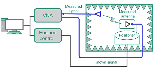
Antenna pattern measurements are also possible. The measurement setup consists of a 2-port VNA, positioner controller, positioner, control PC and an optional over-the-air (OTA) chamber. As it also contains a signal generator as well as a spectrum analyser, a VNA has the additional advantage of combining the functions of two instruments.
The PC adjusts the azimuth and elevation of the positioner via its controller to measure the antenna under test from all angles. This results in a 3D representation of the radiation pattern of the antenna. Once a position is set, one port of the VNA is used to generate the signal that will be radiated via the antenna under test. The radiated signal is then received by the measurement antenna and processed using the second port of the VNA.
This enables the measurements of antenna gain, directivity, effective isotropic radiated power (EIRP), total radiated power (TRP), etc. The measurements can be performed for multiple frequencies during a single rotation of an antenna under test.
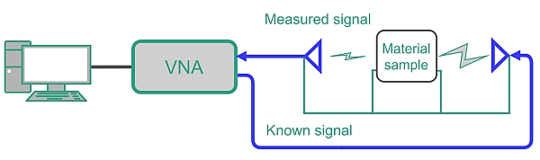
Material Measurement
VNAs can be also used to measure the properties of different dielectric materials, like permittivity or permeability. This can be done by using a VNA, two very directive antennas, and a fixture for the antennas incorporating the sample holder. The sample is placed in the middle between the two antennas, and a sweep is performed over the required frequency band. One directive antenna focuses a narrow beam to the other, in order to maximize measurement precision. Based on the transmission measurement, the material characteristics can be calculated using specialized software.