
- Developers of power systems need to optimize the efficiency of their electronic designs, while guaranteeing their operational safety and reliability. This requires the measurement and analysis of specific signals.
- The MSO Series 4 B oscilloscopes from Tektronix offer signal processing and analysis functions well suited to the testing of power converters, drives and motor control systems.
- Automation of the measurement process also helps to shorten development times.
Author: Andrea Vinci, Senior Technical Marketing Manager, Tektronix
Power analysis of power supply and motor control systems requires the use of several probes and the performance of various calculations. As a result, test configurations can be complex. The analysis software offered by new-generation oscilloscopes can help engineers to carry out measurements faster and more reproducibly. The new Series 4 B MSO is one such oscilloscope. Launching on the market on December 5, 2023 and priced to appeal to many electronics designers, this oscilloscope features a more powerful processor to help power converter designers speed up the measurement analysis process.
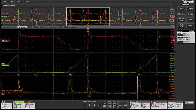
Power measurements on AC/DC and DC/DC converters
Power measurement and analysis packages facilitate measurements on AC/DC and DC/DC converters from input stages, to switching stages, control loops and output stages. The Advanced Power Measurement and Analysis option (4-PWR) is an example of such a package. The software automates the setup process for key power measurements with measurement for AC line inputs for frequency, RMS voltage and current, Crest Factor (voltage and current), true, reactive, and apparent power, power factor and phase. Measurements such as switching loss and magnetic loss help engineers as they make incremental changes to eke out fractions of a percent improvement with the latest wide bandgap power devices. It also allows the in-circuit measurement of Safe Operating Area (SoA) for switching devices. Bode plots may be used to evaluate the stability of power supply control loops. The faster processor in the new version of the 4 Series B, speeds up calculations underlying these measurements for faster update rates.
Measurements support the transition to wide bandgap devices
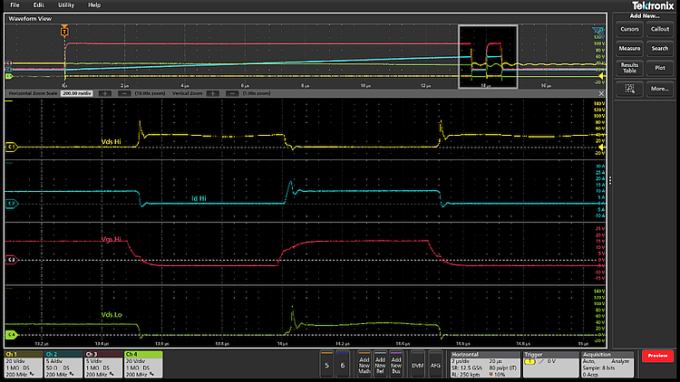
The transition from silicon-to-silicon carbide (SiC) and gallium nitride (GaN) switching devices has put even more pressure on measurement systems. For these devices, accurate assessment of the switching requires much higher measurement bandwidth to accommodate higher slew rates. Until recently, switching measurements on the high side of half-bridge switching stages were almost impossible. Any measurement relative to the switching node suffered from distortion due to the high common mode voltage signals impinging on the differential signal. A relatively new class of probes uses optical isolation to achieve common mode rejection of 80 dB at 1 GHz and higher at lower frequencies. The 4 Series B MSO is compatible with IsoVu optically isolated probes and is thus capable of measuring switching signals of 100V/ns or faster.
Special analysis software for double pulse testing is also available to help designers make the transition to wide bandgap switching technology. The processing power within the instrument is used to automate setups, measurements and calculations to help designers measure switching parameters and on-resistance to support power designers, timing, and diode reverse recovery characteristics.
Three phase power and motor drive analysis
Drive and inverter designers face similar challenges. Most modern motor drive systems use pulse width modulation (PWM) to control the frequency and therefore the speed of a motor. The pulse-width modulation makes stable measurements on these signals challenging. Manually determining the right combination of filters and triggers to achieve stable waveforms is difficult, yet this is a prerequisite for achieving consistent measurements.
They often have three phase outputs which can complicate connections and setups. The wiring configuration determines the calculations used in power analysis, so it is important to understand and select the correct wiring configuration in order to get the expected results. These configurations apply to both the inputs and outputs of motor drives. Incorrect probing of the motor drive system and poor integrity of connections are common sources of errors in making motor drive measurements.
In addition to measuring the output of the drive, measurements to evaluate the performance of the drive’s input stages, such as harmonics, power and power factor are also important. While exporting raw waveforms into a spreadsheet or other analysis software is possible, the process is time-consuming and requires care in performing calculations.
For these reasons getting a good view of a motor drive system with an oscilloscope requires careful setup, stable waveforms and robust measurement algorithms that are provided by application software designed for this purpose. The higher performance of the 4 Series B makes it well-suited for 3-phase measurements for power systems and motor control that were previously only viable on high end scopes.
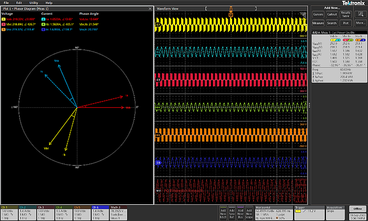
Using 6 channels for measuring 3-phase systems
The output of motor drives and inverters are often 3-wire systems, that is they do not have a neutral conductor or the system is balanced and there is no neutral current. Power in these systems can be accurately measured by using just 2 voltage and 2 current channels on the oscilloscopes, using the “two-wattmeter method”. Two voltage channels and two current channels are needed with the voltage channels connected from phase to phase, with one of the phases acting as a reference. This can be performed with a 4-channel oscilloscope.
However, the inputs to an industrial variable frequency drive (VFD) are more likely to use a 4-wire system with a neutral conductor. In this case three wattmeters should be used. The three-wattmeter configuration requires six oscilloscope channels: three for the voltages and 3 for the currents. Although several oscilloscopes offer 8 input channels, the 4 Series B MSO is one of the few professional-grade oscilloscopes available with 6 analogue inputs.
Test Automation
Like every Tektronix instrument, the 4 Series B MSO is equipped with industry-standard command interfaces and standard communication buses like USB and Ethernet. Over that we layer high-speed APIs, tools, and software to optimize test development time and execution throughput. In order to offer easier instrument control, Tektronix provides access to native instrument drivers that translate instrument commands to familiar constructs in a given programming language. Users can choose from Python, LabVIEW®, CVI, MATLAB, C, C#, .NET or most any other language and have free access to tutorials, scripts, examples, and videos and gain further insights using our programming reference guides.